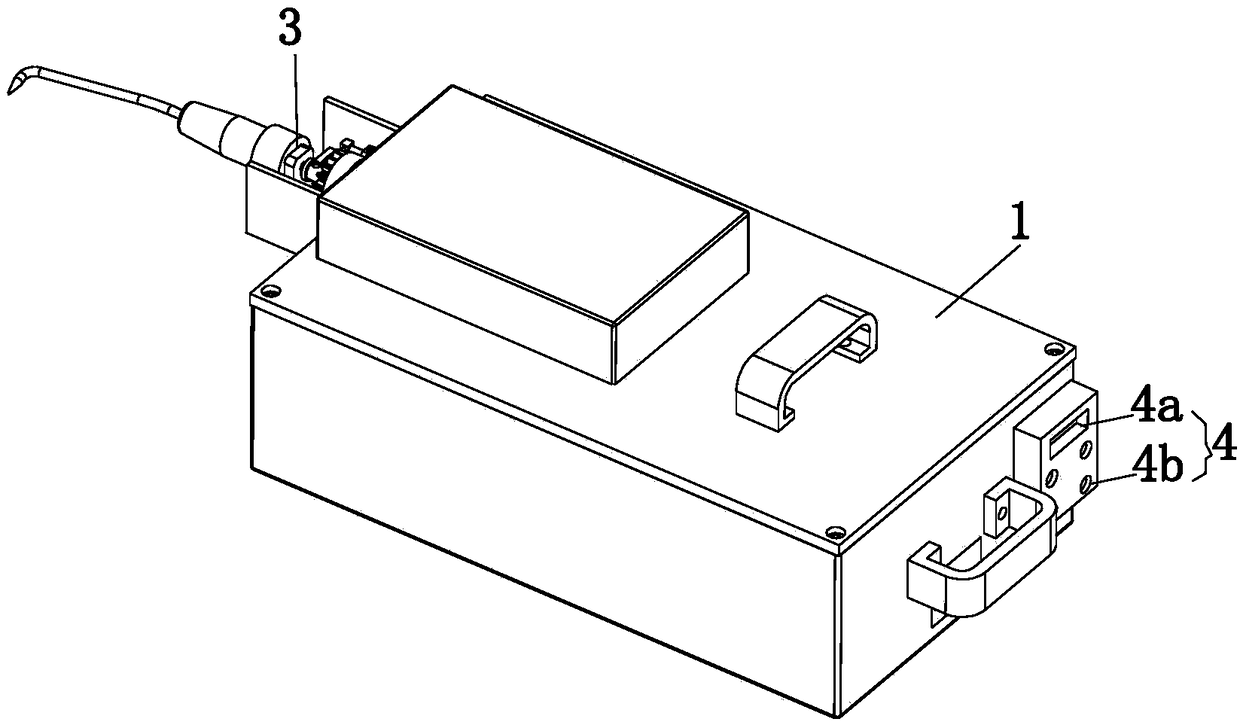
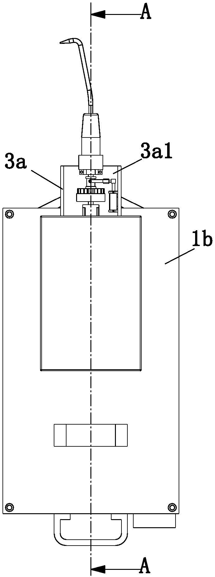
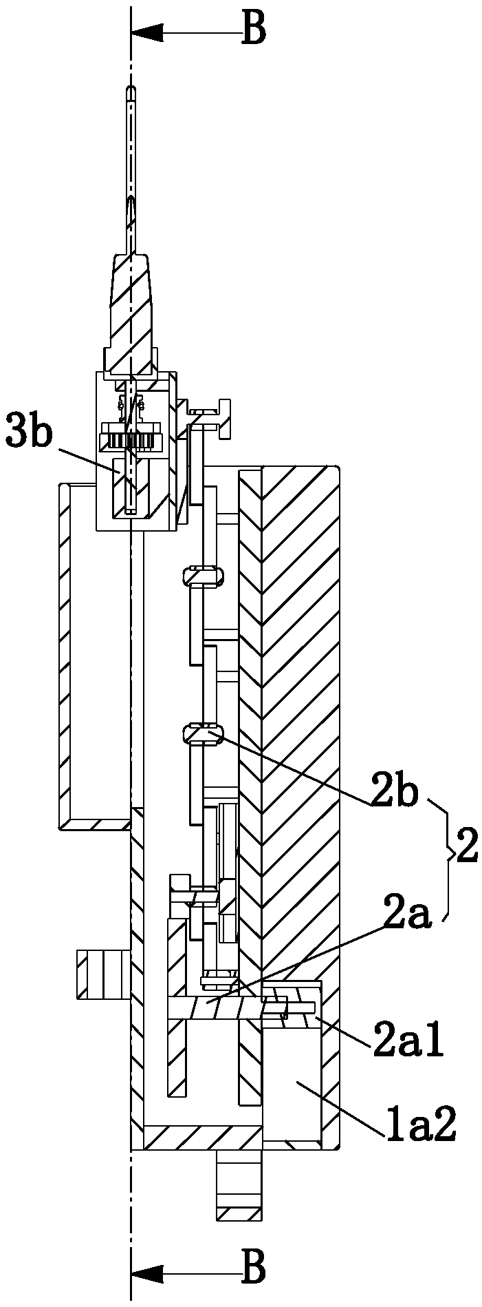
Multifunctional steel bar binding device

A multi-functional technology for steel bar binding, applied in the processing of building materials, construction, building construction, etc., can solve the problems of inability to implement binding operations and reduce the applicability of automatic binding devices, so as to expand the scope of binding and improve the applicability Effect

Active Publication Date: 2019-01-11
广西盛隆钢铁材料研究院有限公司
View PDF6 Cites 4 Cited by
  • Summary
  • Abstract
  • Description
  • Claims
  • Application Information

AI Technical Summary

Problems solved by technology

[0005] The purpose of the present invention is to provide a multi-functional steel bar binding device to solve the problem that the construction personnel cannot

Method used


Image

  • Multifunctional steel bar binding device
  • Multifunctional steel bar binding device
  • Multifunctional steel bar binding device

Examples


Embodiment Construction

[0032] The technical solutions of the present invention will be clearly and completely described below in conjunction with the accompanying drawings. Apparently, the described embodiments are some of the embodiments of the present invention, but not all of them.

[0033] The components of the embodiments of the invention generally described and shown in the figures herein may be arranged and designed in a variety of different configurations. Accordingly, the following detailed description of the embodiments of the invention provided in the accompanying drawings is not intended to limit the scope of the claimed invention, but merely represents selected embodiments of the invention.

[0034] Based on the embodiments of the present invention, all other embodiments obtained by persons of ordinary skill in the art without making creative efforts belong to the protection scope of the present invention.

[0035] In the description of the present invention, it should be noted that the...


PUM


Abstract

The invention discloses a multifunctional steel bar binding device, which belongs to the technical field of building tools. The multifunctional steel bar binding device includes a handheld bearing part, a positioning stretching part and a bearing driving part. The positioning stretching part includes a stretching driving component and an extension linkage component. The bearing driving part includes a driving installation frame, a power transmission component installed on the top of the driving installation frame and a steel tie installation component in butt joint with the output end of the power transmission component. The steel tie installation component is clamped to and matched with the power transmission component. A control part is arranged at the side of the handheld bearing part.The stretching driving component and the power transmission component are electrically connected with the control part. The binding of a steel bar at a short distance and the binding of a steel bar ata long distance can be both completed. The applicability of the whole device is improved. Steel bars at different distances and positions can be bound by using the device.

Description

technical field [0001] The invention relates to the technical field of construction tools, in particular to a multifunctional steel bar binding device. Background technique [0002] The binding of steel bar often all is to adopt binding wire, and will use steel bar binding hook when binding steel bar with binding wire, thereby steel bar binding hook is widely used on construction site as a kind of special tool. Most of the existing steel bar binding hooks are composed of a handle at one end and a curved tip at the other end. Through the hook-shaped part on the tip, the binding wire is hooked, and the steel bar binding hook is rotated, and the steel bar can be bound with the binding wire. firm. In the traditional method, steel workers use lashing hooks to tie them manually, which is labor-intensive. The hand holding the tying hook repeats the same action repeatedly, and the workers are prone to fatigue, which affects efficiency. [0003] The patent number is CN103726663A, a...

Claims


Application Information

Patent Timeline
IPC IPC(8): E04G21/12
CPCE04G21/123
Inventor 郭弘时光王国庆
Owner 广西盛隆钢铁材料研究院有限公司
Why Eureka
Try Eureka