Electrical connector

A technology of electrical connectors and contact arms, which is applied in the direction of connections, circuits, and parts of connection devices, etc. It can solve the problems of insufficient stability of the fixing effect, affecting the welding effect of the contacts, and destroying the wall of the cavity, so as to provide contact stability. , Improve the holding effect and increase the effect of positive force

Active Publication Date: 2019-01-11
DEYI PRECISION ELECTRONIC IND CO LTD PANYU
View PDF13 Cites 1 Cited by
  • Summary
  • Abstract
  • Description
  • Claims
  • Application Information

AI Technical Summary

Problems solved by technology

[0003] Chinese patent application CN96198692.1 describes another socket for electrically connecting a chip module to a circuit board, including an insulating shell and contacts assembled in the insulating shell from bottom to top, and the insulating shell has a space for receiving the contacts. The cavity, the contact has a lead receiving part extending upward from a base, including a pair of arms, a surface mount part extending downward from the base and soldered to the circuit board, and two fixing parts extending from the base to both sides, each fixing part Irregular edges or barbs are used at the end of the end to interfere with the wall of the cavity to prevent the contact from exiting the cavity downwards. However, this fixing method will damage the wall of the cavity, and its fixing effect is not stable enough, and it will also cause cracks. Chips affect the welding effect of the contacts

Method used


Image

  • Electrical connector
  • Electrical connector
  • Electrical connector

Examples


Embodiment Construction

[0026] In order to facilitate a better understanding of the purpose, structure, features, and effects of the present invention, the present invention will now be further described with reference to the drawings and specific embodiments.

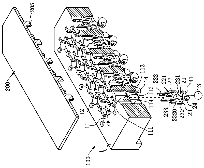
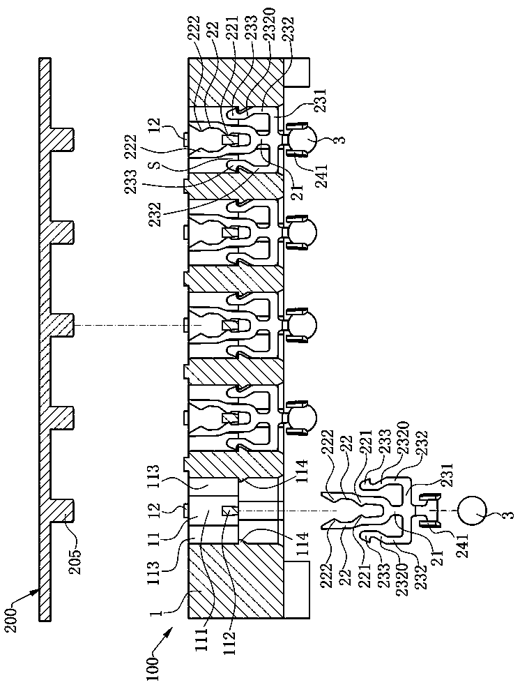
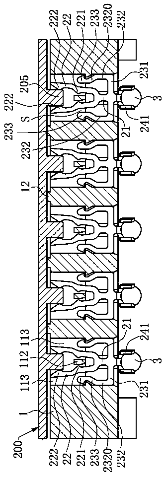
[0027] Such as Figure 1 to Figure 5 Shown is a preferred embodiment of the electrical connector 100 of the present invention, which is used to electrically connect a chip module 200 to a circuit board (not shown), which includes a body 1 and a bottom-up assembly in the The multiple conductive terminals 2 of the main body 1.

[0028] Such as figure 1 , figure 2 with Figure 4 As shown, the main body 1 is made of an insulating material, and has a plurality of receiving holes 11 that penetrate up and down in a matrix arrangement for correspondingly receiving a plurality of the conductive terminals 2 and a plurality of conductive elements 205 of the chip module 200 . Each of the accommodating holes 11 includes a first accommodating space 111 for a...


PUM


Abstract

The invention discloses an electrical connector, comprising: a body, which is provided with at least one receiving hole, wherein the receiving hole is provided with a stopper and at least one protrusion; at least one conductive terminal, which is accommodated in the accommodating hole, the conductive terminal having a base portion, the base portion extendingupwardly to form two contact arms to grip the stopper. The base portion extends upwardly to form at least one retaining arm, the retaining arm including a first arm extending laterally from the base portion, a second arm extending upwardlyfrom the first arm, and a hook portion located at the second arm, the hook portion engaging with the bump to limit downward movement of the conductive terminal. The hook portion engages the bump in the accommodation hole to prevent the conductive terminal from withdrawing downward from the accommodation hole. The hook portion engages the bump in the accommodation hole to prevent the conductive terminal from withdrawing downward from the accommodation hole. The stopper expands the two contact arms to provide a pre-pressure to the two contact arms, increases the forward force of the two contactarms to clamp the conductive element, provides contact stability, and reduces contact resistance.

Description

Technical field [0001] The invention relates to an electrical connector, in particular to an electrical connector for electrically connecting a chip module to a circuit board. Background technique [0002] US Patent US7537461 describes an electrical connector for electrically connecting a chip module to a circuit board, including a body, the body has a plurality of receiving holes, and each receiving hole has a clamping block for connecting the body; and The conductive terminals are assembled in the receiving hole from bottom to top. Each conductive terminal only includes a central part and two beams extending upward from the central part to contact the chip module. The central part is crimped on the circuit board, and the two elastic The arms respectively have a convex portion for clamping the clamping block, and the conductive terminal is fixed in the receiving hole only by the clamping force of the two elastic arms on the clamping block. It is easy for the conductive terminal ...

Claims


Application Information

Patent Timeline
Patent Type & Authority Applications(China)
IPC IPC(8): H01R13/40H01R13/02H01R13/502H01R12/71H01R33/76
CPCH01R12/716H01R13/02H01R13/40H01R13/502H01R33/76
Inventor 何建志
Owner DEYI PRECISION ELECTRONIC IND CO LTD PANYU
Why Eureka
Try Eureka