Electrical connector and manufacturing method thereof

A technology of electrical connectors and abutting parts, which is applied in the field of electrical connectors and its manufacturing, can solve problems such as spot welding failure, affecting use, and deformation at bending places, and achieves good strength and rigidity, is not easy to deform, and enhances the holding effect Effect

Active Publication Date: 2017-11-28
FOXCONN (KUNSHAN) COMPUTER CONNECTOR CO LTD +1
View PDF5 Cites 2 Cited by
  • Summary
  • Abstract
  • Description
  • Claims
  • Application Information

AI Technical Summary

Problems solved by technology

However, the shielding shell of this kind of positive and negative plug-in connectors is formed by stamping and bending, and usually has a bent horizontal line that cannot achieve a good waterproof effect. After use, it will also cause deformation at the bend and cause spot welding failure, which will affect subsequent use

Method used


Image

  • Electrical connector and manufacturing method thereof
  • Electrical connector and manufacturing method thereof
  • Electrical connector and manufacturing method thereof

Examples


Embodiment Construction

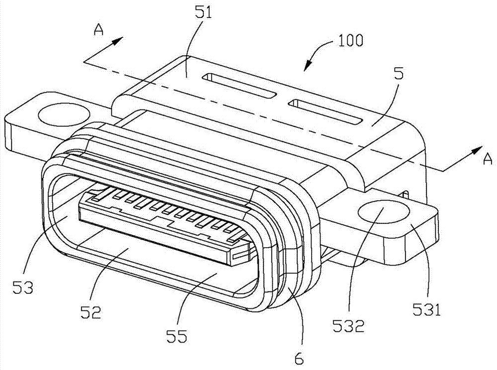
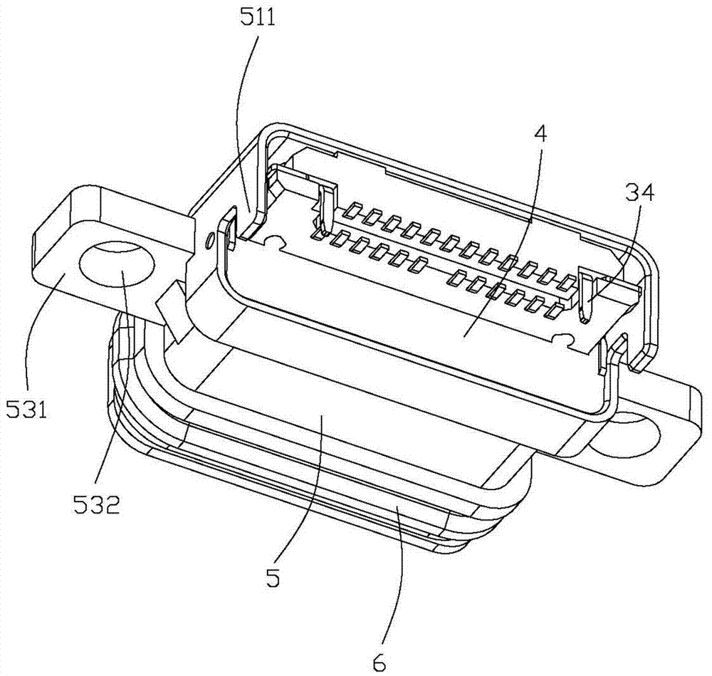
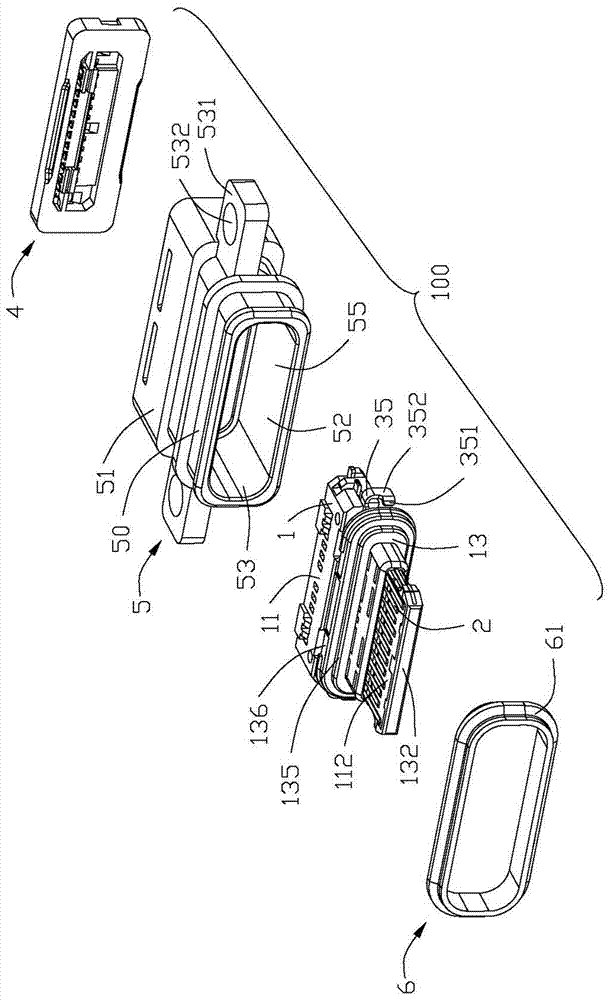
[0027] Below, will combine Figure 1 to Figure 8 A specific implementation manner of the electrical connector 100 of the present invention is introduced. The port where the electrical connector 100 is plugged with the mating connector is defined as the plug-in end. Define a docking direction, a transverse direction, and a vertical direction perpendicular to both the docking direction and the transverse direction, and the plane where the docking direction and the transverse direction are located constitutes a horizontal plane.

[0028] Please refer to Figure 1 to Figure 7 As shown, the electrical connector 100 of the present invention includes an insulating body 1, a plurality of terminals 2 held in the insulating body 1, a metal shielding sheet 3 held in the insulating body 1, a rubber plate 4 formed at the rear end of the insulating body 1, and a sleeve The shielding case 5 outside the insulating body 1 and the waterproof gasket 6 sleeved outside the port of the shielding ...


PUM


Abstract

An electrical connector comprises an insulation body, a plurality of terminals, a metal shielding sheet and a shading shell, wherein the plurality of terminals are fixedly arranged in the insulation body, the metal shielding sheet is fixedly arranged in the insulation body, the shading shell sleeves the insulation body, the metal shielding sheet comprises a retaining sheet, the shading shell is formed by injection molding of metal powder, the retaining sheet is connected with the shading shell by spot welding, the thickness of the shading shell at a welding point is at least two times of the thickness of the retaining sheet, and the shading shell has rigidity twice or more than twice of that of the retaining sheet.

Description

【Technical field】 [0001] The invention relates to an electrical connector and a manufacturing method thereof, in particular to an electrical connector suitable for front and back insertion. 【Background technique】 [0002] The existing positive and negative plug-in connectors include a shielding shell formed by punching and bending metal sheets, an insulating body sleeved in the shielding shell, and a metal shielding sheet held in the insulating body. The metal shielding sheet is provided with spot welding The spot welding part is connected to the shielding shell by spot welding, and the insulating body is clamped by the shielding shell formed by punching and bending the metal sheet, and the spot welding of the spot welding part and the shielding shell is achieved. The purpose of holding in the shielding case. However, the shielding shell of this kind of positive and negative plug-in connectors is formed by stamping and bending, and usually has a bent horizontal line that ca...

Claims


Application Information

Patent Timeline
Patent Type & Authority Applications(China)
IPC IPC(8): H01R13/516H01R13/648H01R13/504H01R43/20
CPCH01R13/504H01R13/516H01R13/648H01R43/20H01R13/5219H01R2107/00H01R13/6585H01R24/60H01R43/005H01R4/28H01R13/426H01R13/5202
Inventor 王财源
Owner FOXCONN (KUNSHAN) COMPUTER CONNECTOR CO LTD
Why Eureka
Try Eureka