
The adapter

A technology of adapters and conductive terminals, which is applied in the field of electrical connectors, can solve problems such as current line confusion, inability to realize predetermined functions and limitations of equipment modules, and achieve the effect of low cost

Pending Publication Date: 2019-01-11
AMPHENOL PCD SHENZHEN
View PDF0 Cites 2 Cited by
  • Summary
  • Abstract
  • Description
  • Claims
  • Application Information

AI Technical Summary

Problems solved by technology

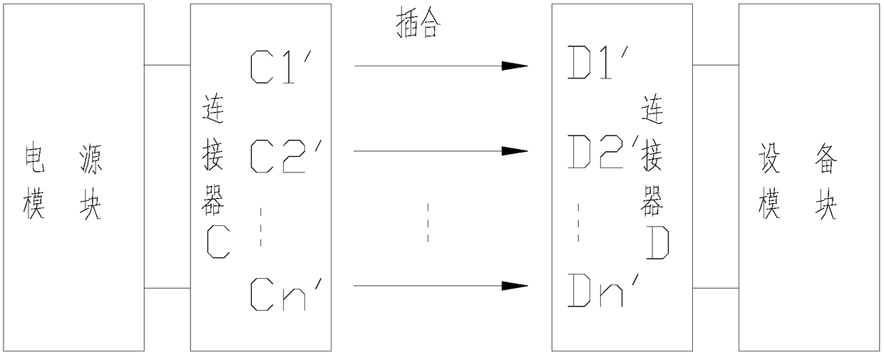
like figure 1 As shown, this traditional connection method limits the line conduction mode, and the mating position and direction of the connector are usually unique, and it is a one-to-one connection. For example, the contact terminal C1' on the connector C corresponds to the connector The contact terminal D1' on D, the contact terminal C2' on the connector C corresponds to the contact terminal D2' on the connector D, and so on, the contact terminal Cn' corresponds to the contact terminal Dn'
[0003] When the power module remains unchanged and the function of the equipment module is expanded, the electrical functions of some contact terminals of the connector on the equipment module will change. At this time, there is no one-to-one correspondence between connectors C and D For example, the contact terminal C1' on the connector C needs to correspond to the contact terminal D2' on the connector D, instead of the contact terminal D1'; the contact terminal C2' on the connector C needs to correspond to the contact terminal on the connector D D1', instead of contact terminal D2'; at this time, plugging connectors C and D will cause confusion in the current circuit, and the predetermined function of the equipment module cannot be realized

Method used


Image

  • The adapter
  • The adapter
  • The adapter

Examples


Embodiment Construction

[0031] Below, the present invention will be further described in conjunction with the accompanying drawings and specific implementation methods. It should be noted that, under the premise of not conflicting, the various embodiments described below or the technical features can be combined arbitrarily to form new embodiments. .

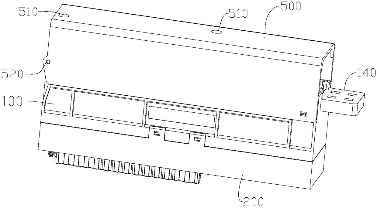
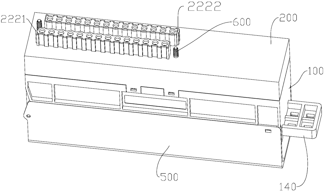
[0032] Please refer to Figure 2-12 , an adapter provided by an embodiment of the present invention includes a first interface assembly 100, a second interface assembly 200 and a circuit board assembly 300, the first interface assembly 100 and the second interface assembly 200 are respectively arranged on two opposite sides of the circuit board assembly 300 On the side, the first interface assembly 100 includes several first conductive terminals 110 arranged at intervals, the second interface assembly 200 includes several second conductive terminals 210 arranged at intervals, and a part of the second conductive terminals 210 pass through the circuit bo...


PUM


Abstract

An adapter disclosed in the invention includes a first interface assembly, a second interface assembly and a circuit board assembly, the first interface assembly and the second interface assembly arerespectively arranged on two opposite sides of the circuit board assembly, the first interface assembly includes a plurality of spaced apart first conductive terminals, The second interface assembly includes a plurality of spaced apart second conductive terminals, a portion of which are electrically connected to the same number of first conductive terminals through the circuit board assembly, andat least two second conductive terminals are electrically connected to the same number of first conductive terminals in a staggered manner. When the function of the device module is expanded, the adapter provided by the invention can realize the circuit connection between the device module and the power module without changing the interface of the device module or the power module, and the cost islow.

Description

technical field [0001] The invention relates to the technical field of electrical connectors, in particular to an adapter. Background technique [0002] When terminal equipment users realize the connection between the power module and the equipment module, they usually use a single connector interface, and the connector C assembled on the power module and the connector D assembled on the equipment module are mated with each other to realize The connectivity of the circuit. Such as figure 1 As shown, this traditional connection method limits the line conduction mode, and the mating position and direction of the connector are usually unique, and it is a one-to-one connection. For example, the contact terminal C1' on the connector C corresponds to the connector The contact terminal D1' on D, the contact terminal C2' on the connector C corresponds to the contact terminal D2' on the connector D, and so on, the contact terminal Cn' corresponds to the contact terminal Dn'. [00...

Claims


Application Information

Patent Timeline
Patent Type & Authority Applications(China)
IPC IPC(8): H01R31/06H01R27/00H01R13/66
CPCH01R13/665H01R27/00H01R31/065
Inventor 刘常明牛秋菊
Owner AMPHENOL PCD SHENZHEN
Learn More