
A positioning carrier for stereoscopic electronic component

A technology for electronic components and positioning carriers, applied in the direction of electrical components, electrical components, etc., can solve problems such as improper operation techniques, low installation efficiency of electronic components, and reduced work efficiency

Pending Publication Date: 2019-01-11
KUNSHAN DONGYE ELECTRONICS
View PDF0 Cites 0 Cited by
  • Summary
  • Abstract
  • Description
  • Claims
  • Application Information

AI Technical Summary

Problems solved by technology

[0004] 1. Positioning refers to ring-shaped electronic components through a jig. The jig is usually punched on a metal plate to form a positioning hole, and then the electronic component is directly positioned in the positioning hole. The existing problem is that the installation efficiency of the electronic component is low
Using this method, due to factors such as improper operation techniques, it is easy to cause damage to electronic components, waste time and manpower, and reduce work efficiency

Method used


Image

  • A positioning carrier for stereoscopic electronic component
  • A positioning carrier for stereoscopic electronic component
  • A positioning carrier for stereoscopic electronic component

Examples


Embodiment Construction

[0029] The present invention will be more fully understood from the following detailed description, which should be read in conjunction with the accompanying drawings. Detailed embodiments of the present invention are disclosed herein; however, it is to be understood that the disclosed embodiments are merely exemplary of the invention, which may be embodied in various forms. Therefore, specific functional details disclosed herein are not to be interpreted as limiting, but merely as a basis for the claims and as a teaching to one skilled in the art that, in fact, any suitably detailed embodiment may differ in any suitably detailed embodiment. The manner employs the representative basis of the present invention.

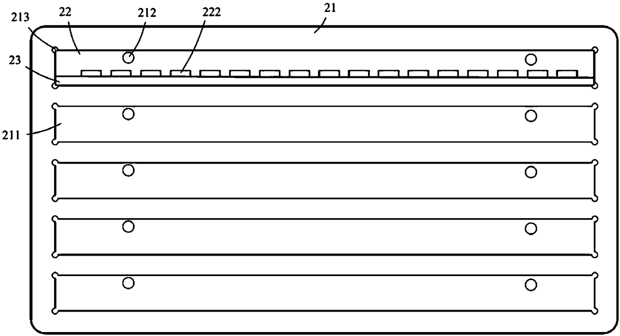
[0030] combine Figure 3-6 As shown, an embodiment of the present application provides a positioning carrier for three-dimensional electronic components, including a substrate 21 , a positioning block 22 and a retaining bar 23 .

[0031] The surface of the substrate ...


PUM


Abstract

The invention discloses a positioning carrier of a stereoscopic electronic component, which comprises a substrate with a card slot arranged in a surface thereof; a positioning block fitting the card slot and provided with at least one position slot for positioning that electronic component, and the top end of each position slot being respectively provided with an SMT window, and the SMT window iscommunicated with the positioning slot; a stopper strip formed on one side of the positioning block and surrounding the positioning block to form the positioning groove. A surface of each substrate ofthat invention can be arrayed with a plurality of strip-like card slot, and the positioning of the electronic components can be realized through a positioning block and a stopper beforehand when assemble, and after the electronic components are loaded, each positioning block and the stopper can form an integral body, so that the electronic components can be assembled with the substrate more efficiently.

Description

technical field [0001] The present application relates to the field of semiconductor technology, in particular to a positioning carrier for three-dimensional electronic components. Background technique [0002] combine figure 1 with 2 As shown, it refers to a ring-shaped electronic component 10 , the circuit board of which is in the shape of a ring as a whole, and has at least one SMT area 101 on its surface. [0003] Surface mount technology (SurfaceMountTechnology, SMT), which is a non-lead or short-lead surface mount components mounted on the surface of the area 101 to be SMT, by reflow soldering or dip soldering and other methods to solder and assemble the circuit assembly technology. The premise of the implementation of circuit assembly and connection technology is: securely position the electronic components, otherwise it is very easy to cause damage to the electronic components, and the current common SMT installation methods are: [0004] 1. Positioning refers to ...

Claims


Application Information

Patent Timeline
IPC IPC(8): H05K13/04
CPCH05K13/046
Inventor 王海浪
Owner KUNSHAN DONGYE ELECTRONICS
Features
  • Generate Ideas
  • Intellectual Property
  • Life Sciences
  • Materials
  • Tech Scout
  • Unparalleled Data Quality
  • Higher Quality Content
  • 60% Fewer Hallucinations
Learn More