IoT (Internet of Things) based rotating disk type hinge punching device

A punching device and turntable technology, which is applied in the direction of boring/drilling, drilling/drilling equipment, boring machine/drilling machine parts, etc., can solve the problems of increasing the waste of human resources and increasing the labor intensity of workers, and achieve the goal of drilling Excellent hole effect and waste reduction effect

Inactive Publication Date: 2019-01-15
魏赛尔
View PDF14 Cites 7 Cited by
  • Summary
  • Abstract
  • Description
  • Claims
  • Application Information

AI Technical Summary

Problems solved by technology

[0003] Hinge drilling is a necessary step in the production of hinges. In the prior art, manual drilling or semi-automatic drilling with machine

Method used


Image

  • IoT (Internet of Things) based rotating disk type hinge punching device
  • IoT (Internet of Things) based rotating disk type hinge punching device
  • IoT (Internet of Things) based rotating disk type hinge punching device

Examples


Embodiment 1

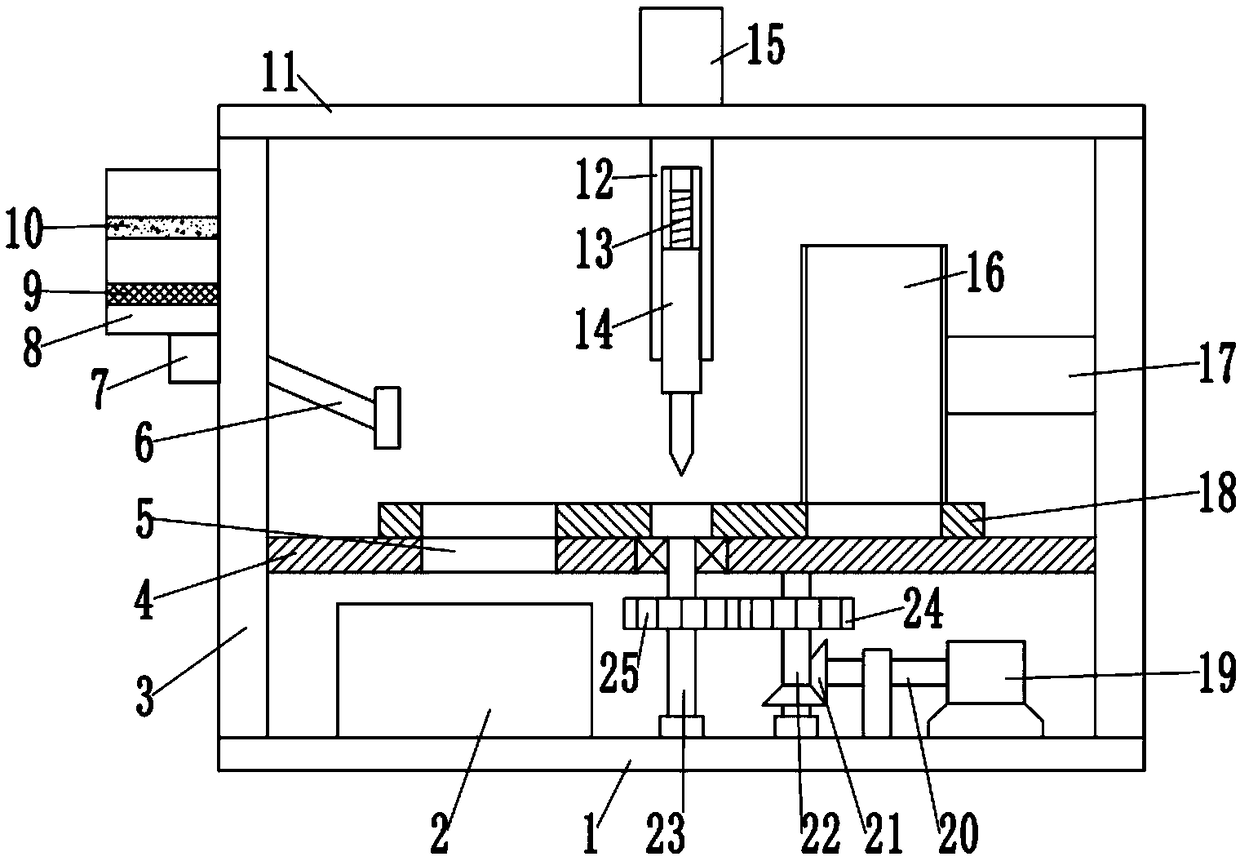
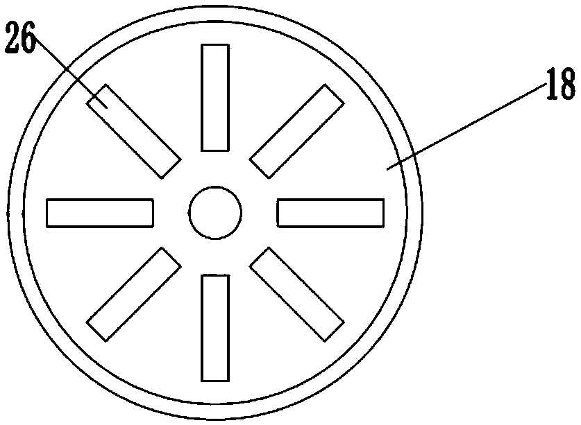
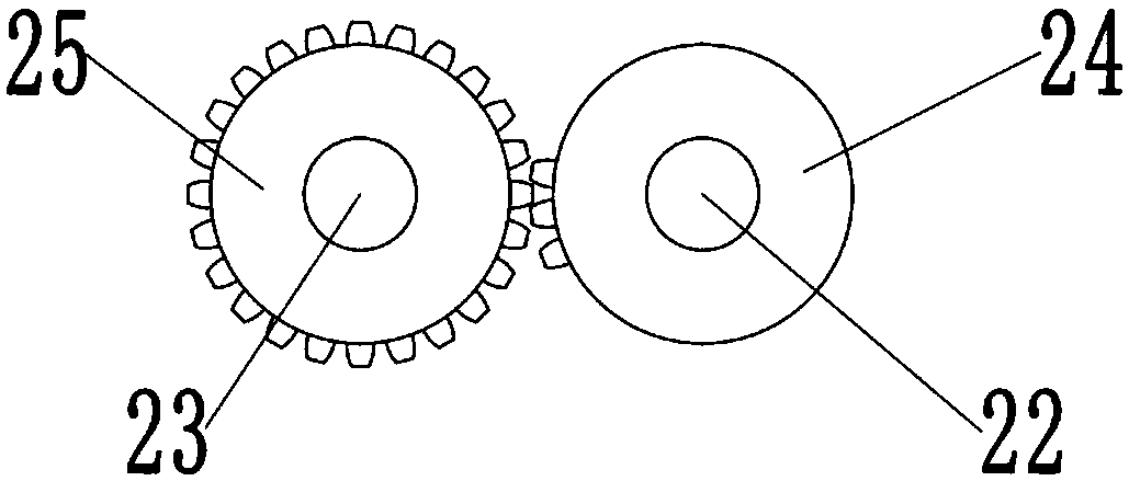
[0023] see Figure 1~3 , in an embodiment of the present invention, a turntable hinge punching device based on the Internet of Things includes a bottom plate 1 and a turntable 18; two side plates 3 are fixedly fixed on the left and right sides of the bottom plate 1, and the top of the side plate 3 The top plate 11 is fixedly installed, and the partition plate 4 is also fixedly installed between the two side plates 3; the turntable 18 is installed on the bottom plate 1 through the rotation of the third rotating shaft 23, and the lower side of the turntable 18 is close to the upper side of the partition plate 4 , and the dividing plate 18 is evenly provided with a number of placement grooves 26 for placing hinges to be punched, eight placement grooves 26 are arranged symmetrically, and the placement grooves 26 are through groove structures; the upper right side of the turntable 18 is provided with a Feeding pipe 16, feeding pipe 16 is fixedly installed on the side plate 3 by bra...

Embodiment 2

[0030] see Figure 1~3 , in an embodiment of the present invention, a turntable hinge punching device based on the Internet of Things includes a bottom plate 1 and a turntable 18; two side plates 3 are fixedly fixed on the left and right sides of the bottom plate 1, and the top of the side plate 3 The top plate 11 is fixedly installed, and the partition plate 4 is also fixedly installed between the two side plates 3; the turntable 18 is installed on the bottom plate 1 through the rotation of the third rotating shaft 23, and the lower side of the turntable 18 is close to the upper side of the partition plate 4 , and the dividing plate 18 is evenly provided with a number of placement grooves 26 for placing hinges to be punched, eight placement grooves 26 are arranged symmetrically, and the placement grooves 26 are through groove structures; the upper right side of the turntable 18 is provided with a Feeding pipe 16, feeding pipe 16 is fixedly installed on the side plate 3 by bra...


PUM


Abstract

The invention discloses an IoT based rotating disk type hinge punching device. The device comprises a base plate and a rotating disk; two side plates are symmetrically fixedly mounted in the left andright sides of the base plate respectively, a top plate is fixedly mounted in the tops of the side plates, and a separator plate is fixedly mounted between the side plates; the rotating disk is rotationally mounted on the base plate via a third rotating shaft, the lower side of the rotating disk clings to the upper side of the separator plate, and standing grooves for placing a hinged to be punched are formed uniformly in the separator plate; the bottom of the top plate is rotationally and fixedly provided with a frame, the frame is internally rotationally provided with a screw, the lower endof the screw is in threaded connection with a thread sleeve, the lower end of the thread sleeve is fixedly provided with a drilling device for punching, and the drilling device positioned above the standing grooves in the back side the rotating disk, and the left side of the separator plate is provided with a discharging opening under the standing grooves. Punching is completed automatically, manual punching is not needed, waste of labor resources can be reduced, and the punching effect is good.

Description

technical field [0001] The invention relates to a punching device, in particular to a turntable hinge punching device based on the Internet of Things. Background technique [0002] A hinge, also known as a hinge, is a mechanical device used to connect two solids and allow relative rotation between them. Hinges can be constructed of movable components, or of collapsible material. Hinges are mainly installed on doors and windows, and hinges are more installed on cabinets. According to the classification of materials, they are mainly divided into stainless steel hinges and iron hinges; in order to let people enjoy better, hydraulic hinges (also known as damping hinges) appeared. Its characteristic is that it brings a buffer function when the cabinet door is closed, which minimizes the noise caused by the collision with the cabinet body when the cabinet door is closed. [0003] Hinge punching is a necessary step in hinge production. In the prior art, manual punching or semi-au...

Claims


Application Information

Patent Timeline
IPC IPC(8): B23B41/00B23B47/00B23Q1/50
CPCB23B41/00B23B47/00B23Q1/50
Inventor 魏赛尔
Owner 魏赛尔
Why Eureka
Try Eureka