
Grinding and polishing equipment for plastic parts

A technology of parts and plastics, applied in the field of plastic parts grinding and polishing equipment, can solve problems such as uneven grinding, unstable manual operation, damage to plastic parts, etc., achieve reasonable structural design, realize automatic processing work, and reduce human resources the effect of consumption

Active Publication Date: 2020-11-10
陈俊
View PDF7 Cites 0 Cited by
  • Summary
  • Abstract
  • Description
  • Claims
  • Application Information

AI Technical Summary

Problems solved by technology

[0002] With the continuous development of the economic level, the continuous increase of per capita income, the continuous improvement of people's purchasing power, the continuous improvement of the market demand for automobiles, and the continuous development of the field of auto parts processing, in the process of automobile processing, it is necessary to use For many sleeve-type plastic parts, after the plastic parts are produced from the mold, the inner wall of the plastic parts needs to be finished, that is, the work of removing burrs and polishing the uneven parts, so as to ensure that its quality can meet the needs of automobile production , in the actual finishing process, it needs to be done manually. This kind of processing operation method not only needs to consume more human resources, but also due to the instability of manual operation, it is easy to cause uneven grinding, which will cause plastic parts damage, resulting in economic loss
[0003] According to the needs of actual production, traditional processing methods can no longer meet the current actual production needs, so we designed plastic parts grinding and polishing equipment to solve the above problems

Method used


Image

  • Grinding and polishing equipment for plastic parts
  • Grinding and polishing equipment for plastic parts
  • Grinding and polishing equipment for plastic parts

Examples


Embodiment Construction

[0024] The following will clearly and completely describe the technical solutions in the embodiments of the present invention with reference to the accompanying drawings in the embodiments of the present invention. Obviously, the described embodiments are only some, not all, embodiments of the present invention.

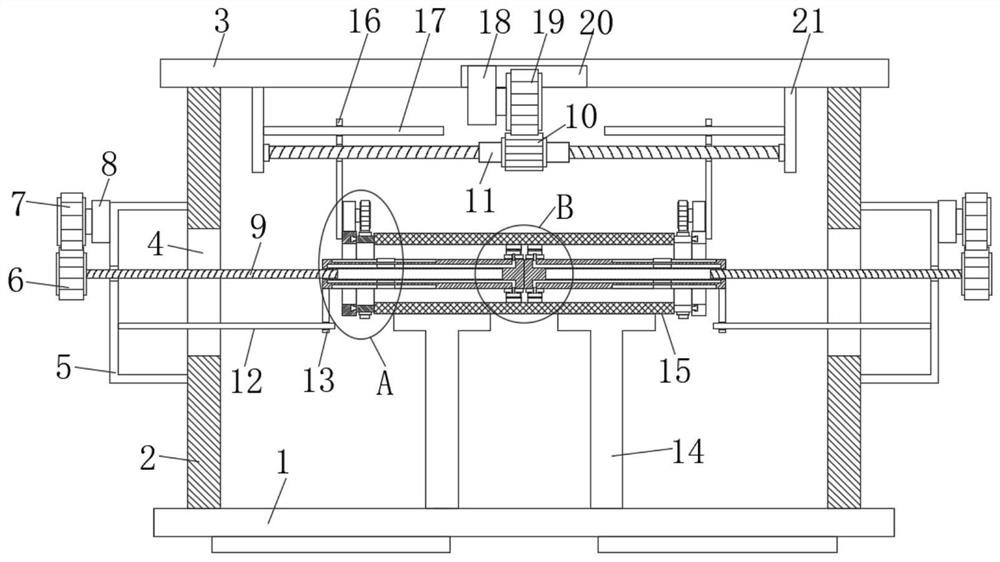
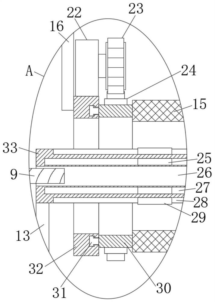
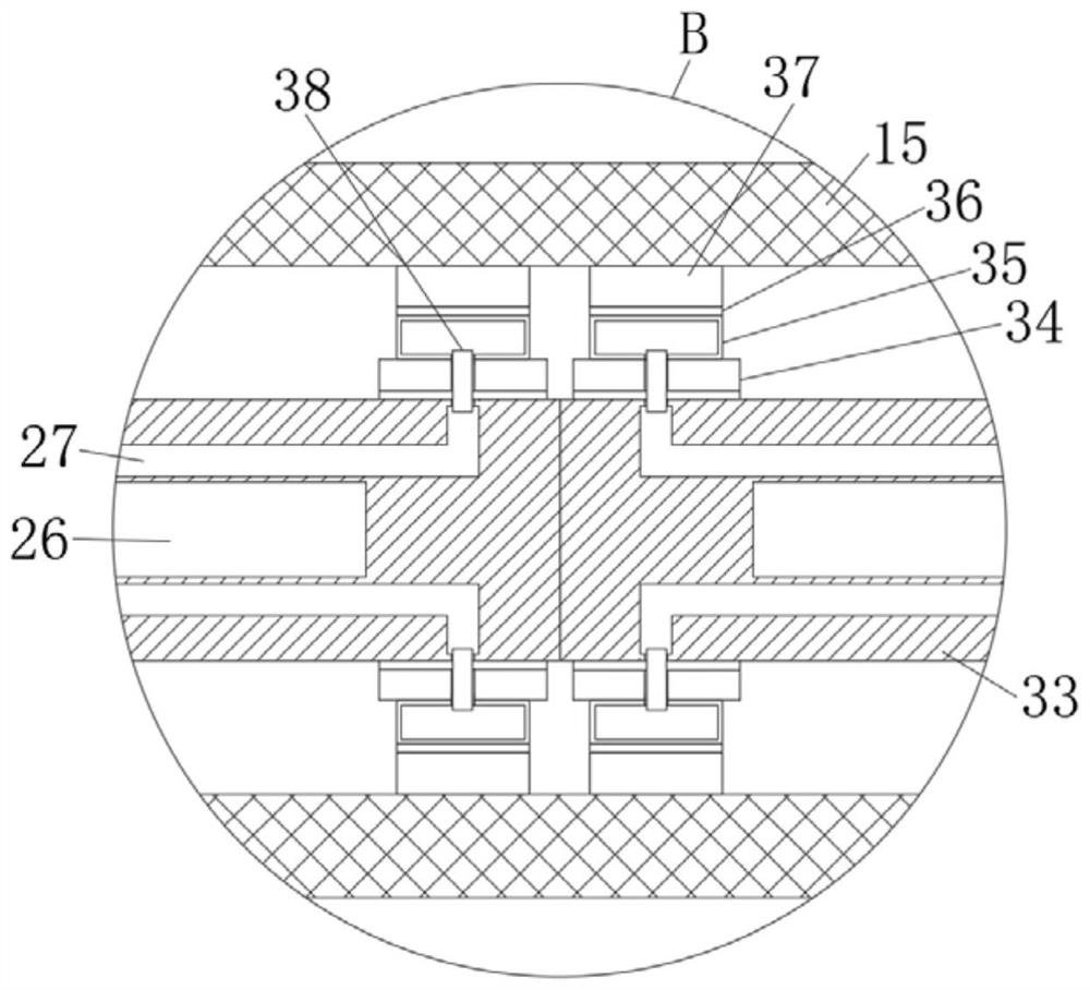
[0025] refer to Figure 1-4 , plastic parts grinding and polishing equipment, including a base 1, the bottom side wall of the base 1 is provided with a plurality of support blocks, the bottom side walls of the multiple support blocks are provided with anti-skid lines, and the upper end of the base 1 is symmetrically provided with two The support plate 2, the upper ends of the two support plates 2 are jointly fixedly connected with the first fixed plate 3, and the upper end of the base 1 is symmetrically provided with two support platforms 14, and the upper ends of the two support platforms 14 are jointly placed with the workpiece 15 to be processed. The lower end of ...


PUM


Abstract

The invention discloses a plastic component grinding and polishing device which comprises a base. The upper end of the base is symmetrically provided with two support plates, the upper ends of the twosupport plates are fixedly connected to a first fixed plate, the upper end of the base is symmetrically provided with two support tables, and a workpiece to be processed is placed on the upper ends of the two support tables. The lower end of the first fixed plate is provided with a moving device, the opposite side walls of the moving device are fixedly connected to positioning devices, the opposite side walls of the two positioning devices press against the side walls of two ends of the workpiece to be processed, communicating holes pass through the opposite side walls of the two support plates, and the side walls of opposite ends of the two support plates are fixedly connected to telescopic devices. The structural design of the plastic component grinding and polishing device is reasonable, the consumption of human resources can be reduced, the automatic processing work is achieved, the position of a grinding block is self-adjusted, and the grinding degree of the inner side wall of the workpiece to be processed can be adjusted according to actual needs.

Description

technical field [0001] The invention relates to the technical field of parts processing, in particular to grinding and polishing equipment for plastic parts. Background technique [0002] With the continuous development of the economic level, the continuous increase of per capita income, the continuous improvement of people's purchasing power, the continuous improvement of the market demand for automobiles, and the continuous development of the field of auto parts processing, in the process of automobile processing, it is necessary to use For many sleeve-type plastic parts, after the plastic parts are produced from the mold, the inner wall of the plastic parts needs to be finished, that is, the work of removing burrs and polishing the uneven parts, so as to ensure that its quality can meet the needs of automobile production , in the actual finishing process, it needs to be done manually. This kind of processing operation method not only needs to consume more human resources,...

Claims


Application Information

Patent Timeline
Patent Type & Authority Patents(China)
IPC IPC(8): B24B9/20B24B5/40B24B5/50B24B41/06B24B47/22B24B41/04B24B47/12B24B47/16
CPCB24B5/40B24B5/50B24B9/20B24B41/04B24B41/06B24B47/12B24B47/16B24B47/22
Inventor 陈俊
Owner 陈俊
Learn More