
Charging device for new energy vehicle

A new energy vehicle and charging device technology, which is applied to electric vehicle charging technology, charging stations, electric vehicles, etc., can solve the problems of falling off of the charging gun, hidden dangers of users, affecting the charging work, etc., and achieves reasonable structural design and reduced safety. hidden effect

Active Publication Date: 2019-08-16
安徽省智慧交通科技有限责任公司
View PDF7 Cites 6 Cited by
  • Summary
  • Abstract
  • Description
  • Claims
  • Application Information

AI Technical Summary

Problems solved by technology

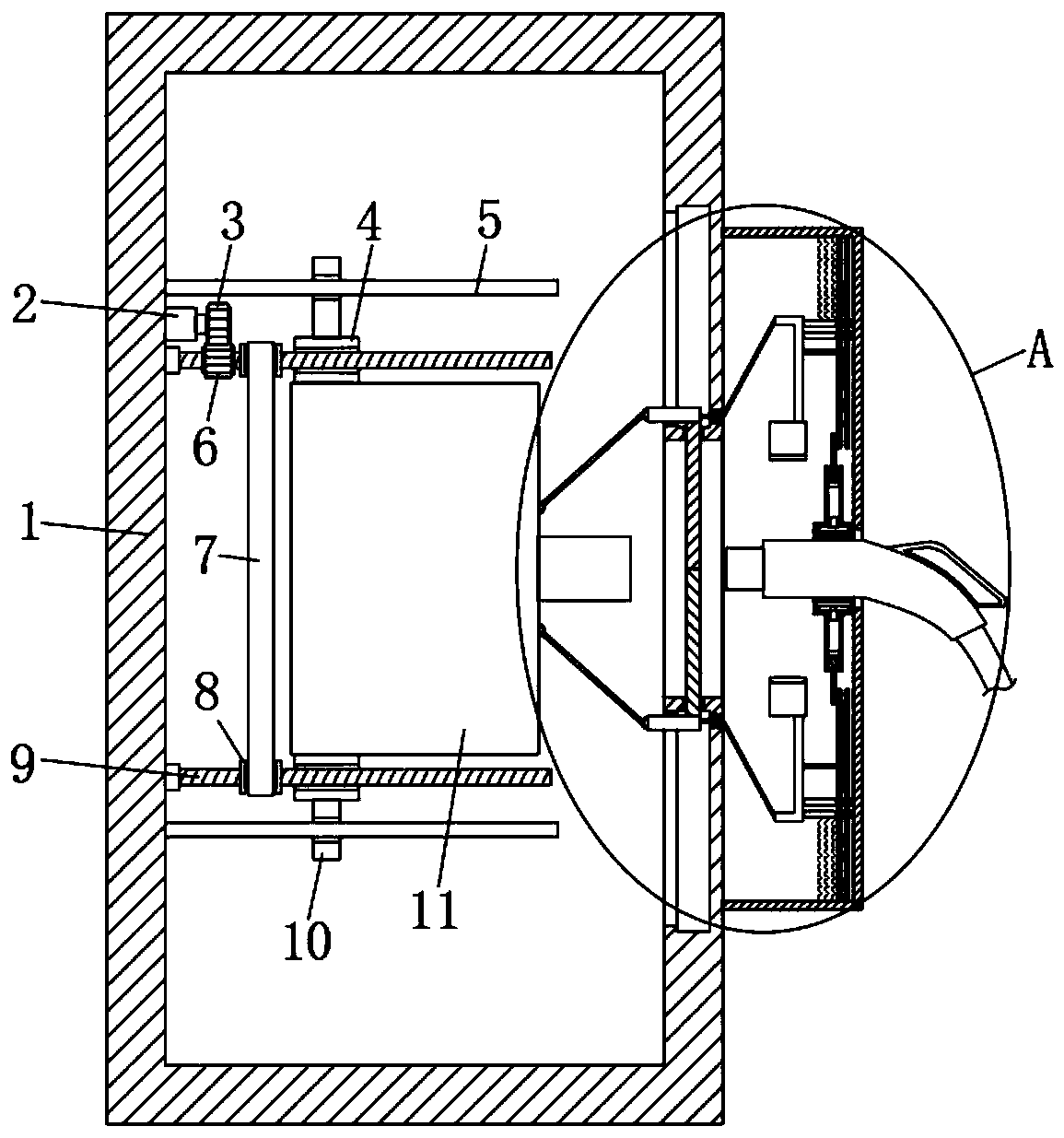
[0003] New energy vehicles are mainly electric vehicles. After electric vehicles are used, they need to be charged to ensure their normal driving. At present, when charging is required, users need to manually insert the charging gun into the charging port of the charging pile. , and connect it to the charging power source, such an operation method will cause certain safety hazards to the user, and when the existing charging gun is charging, it is easy to cause the charging gun to fall off because there is no limit measure, thus Affect the normal charging work, so we designed a charging device for new energy vehicles to solve the above problems

Method used


Image

  • Charging device for new energy vehicle
  • Charging device for new energy vehicle
  • Charging device for new energy vehicle

Examples


Embodiment Construction

[0026] The following will clearly and completely describe the technical solutions in the embodiments of the present invention with reference to the accompanying drawings in the embodiments of the present invention. Obviously, the described embodiments are only some, not all, embodiments of the present invention.

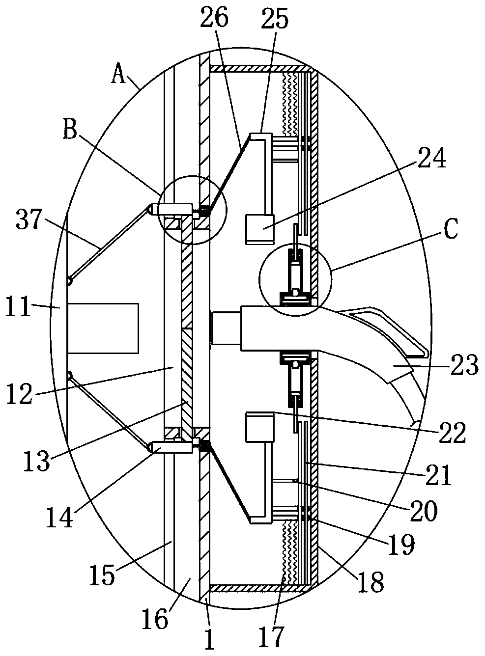
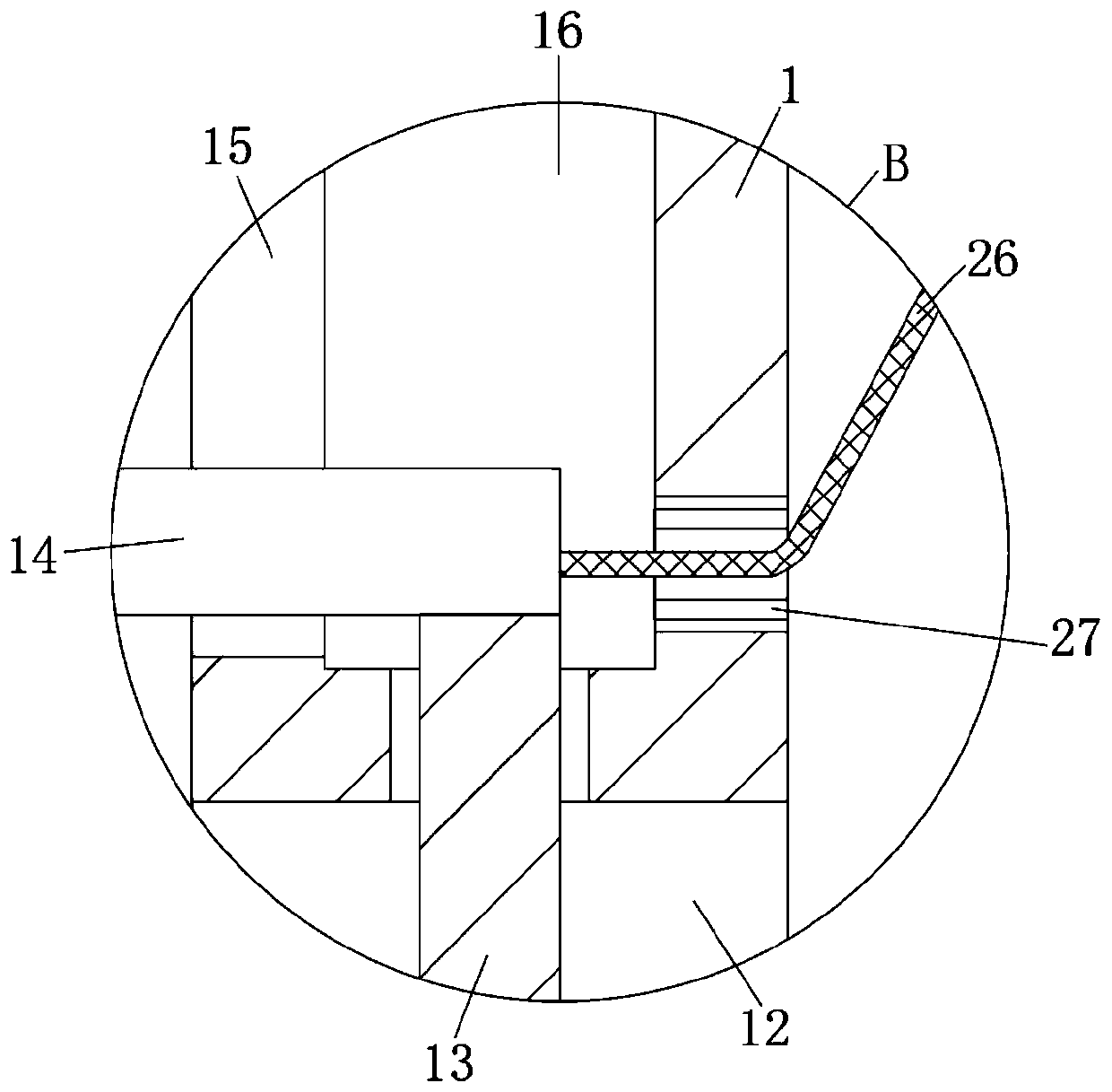
[0027] refer to Figure 1-5 , a charging device for new energy vehicles, comprising a box body 1, an installation cavity is provided inside the box body 1, a charging power supply 11 is provided in the installation cavity, and a moving mechanism is connected between the charging power supply 11 and the inner side wall of the installation cavity, The moving mechanism includes two threaded rods 9 that are rotatably connected to the inner wall of the installation cavity, and the outer walls of the two threaded rods 9 are fixedly connected with a transmission wheel 8, and a transmission belt 7 is connected between the two transmission wheels 8, and the transmission wheel ...


PUM


Abstract

The invention discloses a charging device for a new energy vehicle. The charging device for the new energy vehicle comprises a box body; a mounting cavity is formed in the box body; a charging power supply is arranged in the mounting cavity; a moving mechanism is connected between the charging power supply and the internal side wall of the mounting cavity; a first communication groove communicating with the mounting cavity is arranged in the side wall of the box body in a through manner; two sliding cavities which are arranged with one under the other one are symmetrically formed in the box body; the first communication groove is formed between the two sliding cavities; communication holes communicating with the sliding cavities are formed in the internal side walls of the upper and lowerends of first communication groove in a through manner; and two strip-shaped grooves communicating with the sliding cavities are formed in the internal side walls of the mounting cavities in a throughmanner. According to the charging device for the new energy vehicle, the structural design is reasonable; a user can be prevented from manually connecting a charging gun with the charging power supply; potential safety hazards are reduced; and moreover, stable connection between the charging gun and the charging power supply can be guaranteed; easy falling of the charging gun can be avoided; andnormal charging working can be guaranteed.

Description

technical field [0001] The invention relates to the technical field of new energy vehicles, in particular to a charging device for new energy vehicles. Background technique [0002] In recent years, with the continuous development of the economic level, my country's environmental quality has generally declined. With the continuous enhancement of people's awareness of environmental protection and the support of purchasing policies, new energy vehicles have gradually been accepted by people. It will not emit carbon dioxide and other vehicle exhaust, so as to reduce the environmental pollution caused by vehicle exhaust. [0003] New energy vehicles are mainly electric vehicles. After electric vehicles are used, they need to be charged to ensure their normal driving. At present, when charging is required, users need to manually insert the charging gun into the charging port of the charging pile. , and connect it to the charging power source, such an operation method will cause c...

Claims


Application Information

Patent Timeline
Patent Type & Authority Applications(China)
IPC IPC(8): B60L53/16
CPCB60L53/16Y02T10/70Y02T90/14Y02T10/7072Y02T90/12
Inventor 王莎莎
Owner 安徽省智慧交通科技有限责任公司
Learn More