Movable elbow rotating structure

A technology of rotating structure and movable elbow, applied in the direction of elbow, pipe/pipe joint/pipe fitting, siphon, etc., can solve the problems of no use of installation and disassembly, large diameter of steel ball, easy to be sheared, etc., to reduce costs , weight reduction, easy and quick installation and removal

Active Publication Date: 2019-01-15
JIANGSU ORIENT PETROLEUM MASCH CO LTD
View PDF5 Cites 2 Cited by
  • Summary
  • Abstract
  • Description
  • Claims
  • Application Information

AI Technical Summary

Problems solved by technology

[0002] In the sour working environment, the swivel elbow is mainly used for high-pressure discharge pipelines, input pipelines, well test pipelines or other high-pressure conditions to transport liquid flow, especially in the role of swivel elbows in cementing and fracturing operations. It is very important, and the existing swivel elbow rotating structure is basically a steel ball, and its disadvantages are as follows: firstly, the diameter of the steel ball is relatively large, so the outer diameter of the elbow will increase accordingly; secondly, the number of steel balls is large, so it is less Using installation and disassembly, the main problem in the end is that when the swivel elbow is under high pressure, the steel ball is easily sheared without any buffer protection under high pressure

Method used


Image

  • Movable elbow rotating structure
  • Movable elbow rotating structure
  • Movable elbow rotating structure

Examples


Embodiment Construction

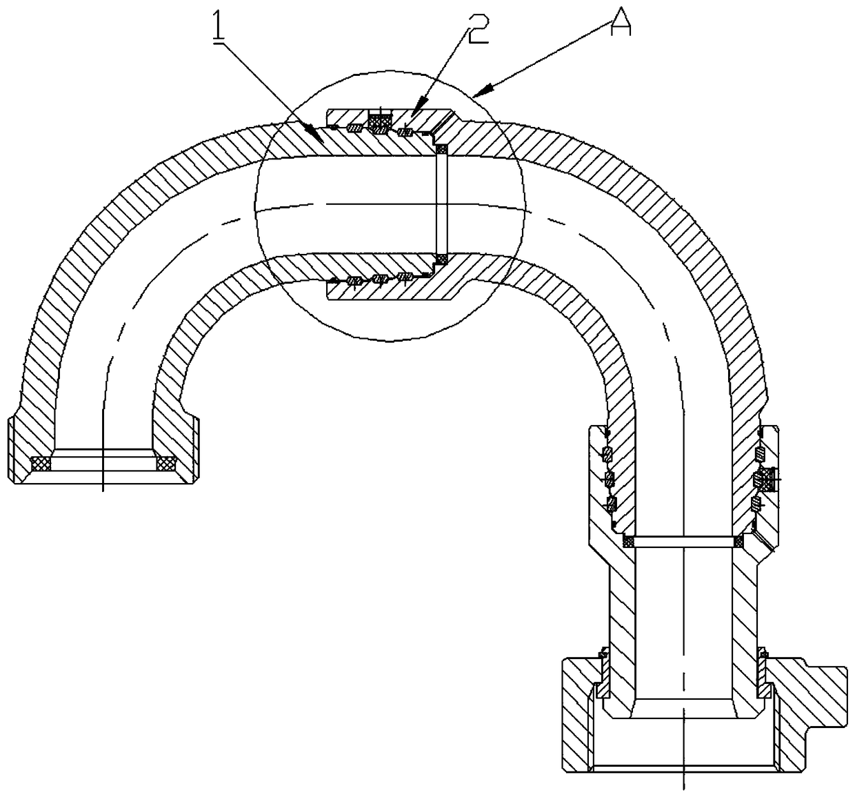
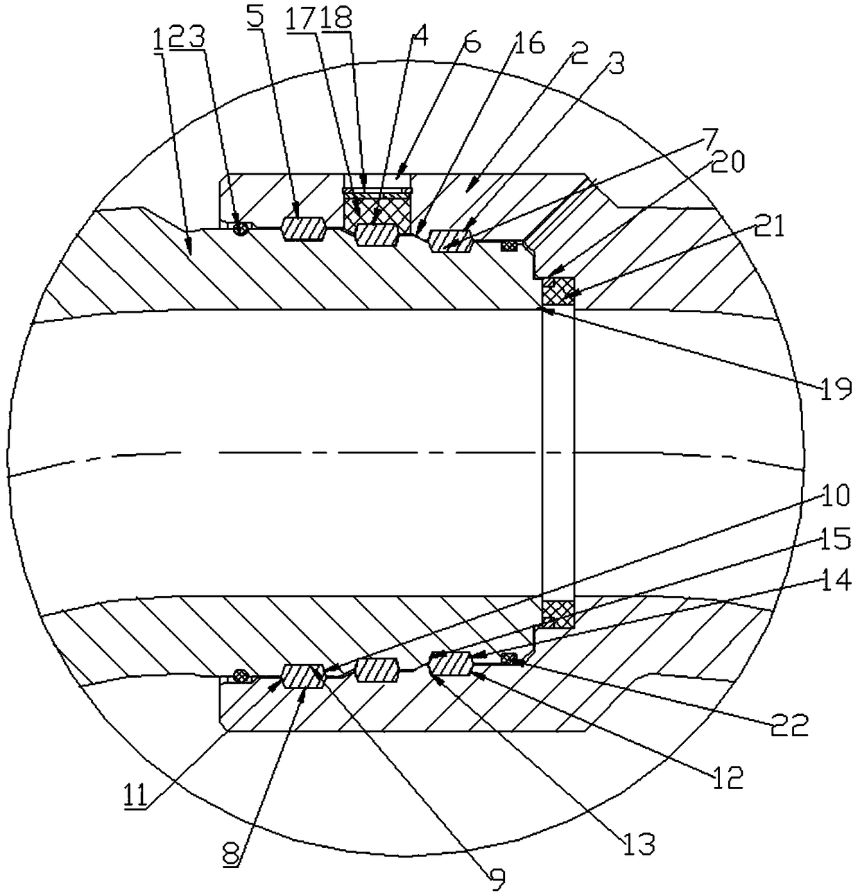
[0022] combine Figure 1 to Figure 7 The swivel elbow rotation structure shown in this embodiment includes the male end 1 of the elbow body and the female end 2 of the elbow body, and the male end 1 of the elbow body is inserted into the female end of the elbow body 2, the female end 2 of the elbow body is provided with three inner trapezoidal slideway grooves located on the mating surface with the male end 1 of the elbow body, which are respectively the first inner trapezoidal grooves arranged in sequence along the axial direction. The slideway groove, the second inner trapezoidal slideway groove and the third inner trapezoidal slideway groove, the outside wall of the male end 1 of the elbow body is provided with an outer trapezoidal slideway corresponding to the inner trapezoidal slideway groove The grooves are respectively the first outer trapezoidal slideway groove, the second outer trapezoidal slideway groove and the third outer trapezoidal slideway groove arranged axiall...


PUM


Abstract

The invention provides a movable elbow rotating structure, comprising a male end of the elbow body and a female end of the elbow body. The female end of the elbow body is provided with three inner trapezoidal slide grooves on a mating surface of the male end of the elbow body. The outer side wall of the male end of the elbow body is provided with outer trapezoidal slide grooves matched with the inner trapezoidal slide grooves in one-to-one correspondence. The outer trapezoidal slide grooves and the inner trapezoidal slide grooves cooperate one-to-one to form three annular chute spaces. The female end of the elbow body is respectively provided with three plug ports communicating with the three annular chute spaces, and the annular chute spaces are filled with a plurality of conical ring blocks arranged in a ring shape. Each conical ring block includes an outer annular surface slidably matched with the inner trapezoidal slide grooves, an inner annular surface slidably matched with the outer trapezoidal slide grooves, and two conical surfaces, a first conical surface and a second conical surface, connected between the outer annular surface and the inner annular surface. The movable elbow rotating structure can effectively save the cost of an elbow and prolong the service life of the movable elbow.

Description

technical field [0001] The invention relates to a swivel elbow, in particular to a swivel elbow rotation structure. Background technique [0002] In the sour working environment, the swivel elbow is mainly used for high-pressure discharge pipelines, input pipelines, well test pipelines or other high-pressure conditions to transport liquid flow, especially in the role of swivel elbows in cementing and fracturing operations. It is very important, and the existing swivel elbow rotating structure is basically a steel ball, and its disadvantages are as follows: firstly, the diameter of the steel ball is relatively large, so the outer diameter of the elbow will increase accordingly; secondly, the number of steel balls is large, so it is less Using installation and disassembly, the most important problem in the end is that when the swivel elbow is under high pressure, the steel ball is easily sheared without any buffer protection under high pressure. [0003] Therefore, there is a...

Claims


Application Information

Patent Timeline
Patent Type & Authority Applications(China)
IPC IPC(8): F16L43/00
CPCF16L43/00
Inventor 阮必春单绍玉
Owner JIANGSU ORIENT PETROLEUM MASCH CO LTD
Why Eureka
Try Eureka