Thermal Decomposition System of Reductant in Selective Catalytic Reduction Device

A reducing agent and selective technology, applied in the direction of exhaust device, muffler device, separation method, etc., can solve the problems of uncontrollable exhaust gas flow, reducing agent leakage, complicated piping structure, etc., to save production costs and equipment costs, reduce The effect of small size and space occupation, fuel cost and air pressure consumption

Active Publication Date: 2019-01-11
DOOSAN ENGINE
View PDF5 Cites 0 Cited by
  • Summary
  • Abstract
  • Description
  • Claims
  • Application Information

AI Technical Summary

Problems solved by technology

[0014] However, the ammonia gas injection method utilizing the reducing agent pyrolysis system requires a large number of additional components compared to the reducing agent direct injection method, and requires arranging many of the above-described components, which has the problem of occupying a large space.
[0015] In addition, conventionally known pyrolysis systems for reducing agents have the following problems: in order to transfer the reducing agent between the various components, the piping configuration is complicated, and the equipment cost increases.
[0016] In addition, conventionally known thermal decomposition systems for reducing agents have the following problems: additional energy (electric power, fuel, air pressure) and costs are required for driving the blower (Blower) and the heating device (Heating Device)
However, Patent Document 1 cannot control the flow rate of the exhaust gas flowing into the inner tube, so it cannot provide an appropriate mixing ratio. If the reducing agent is too large compared to the exhaust gas flow rate, there is a concern that the reducing agent will leak to the outside.

Method used


Image

  • Thermal Decomposition System of Reductant in Selective Catalytic Reduction Device
  • Thermal Decomposition System of Reductant in Selective Catalytic Reduction Device

Examples


Embodiment Construction

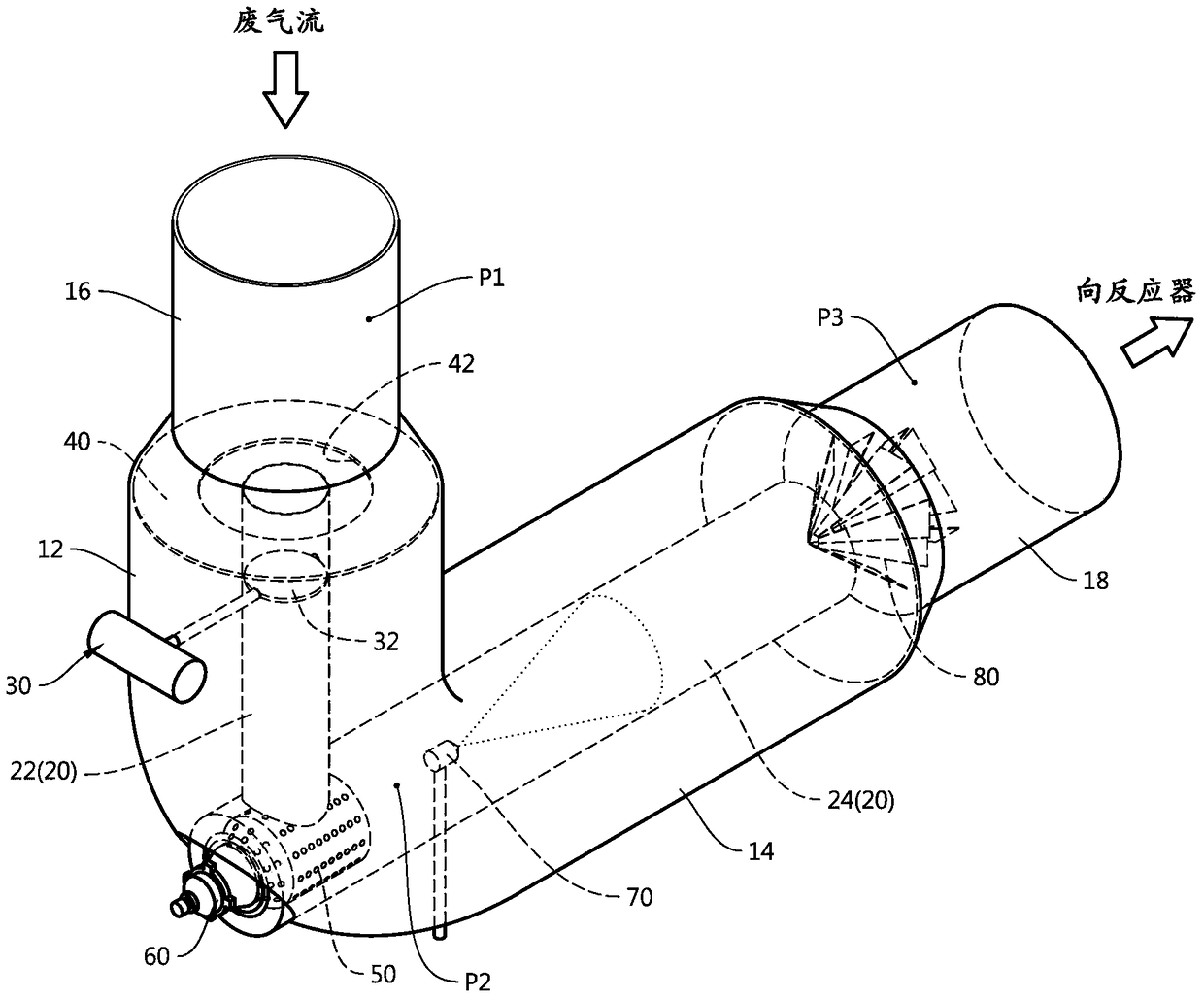
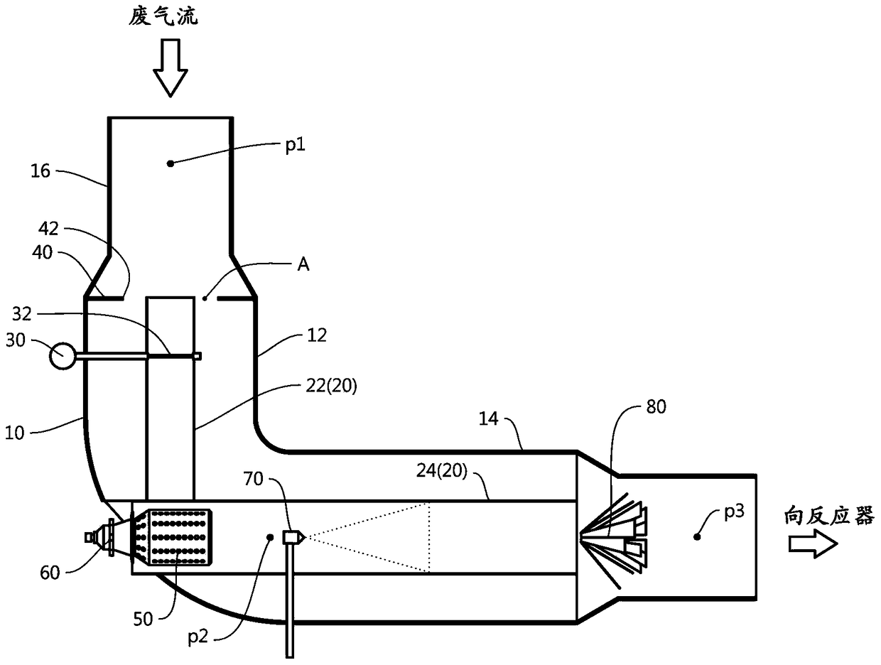
[0042] Reference and attachment Figure 1 With the detailed description of the embodiment, the advantages, features and methods for achieving the present invention are clarified.

[0043] Embodiments of the present invention will be described in detail below with reference to the accompanying drawings. The embodiments described below are presented as examples to facilitate understanding of the present invention, and it should be understood that the present invention can be implemented in various modifications other than the embodiments described here. However, in describing the present invention, when it is judged that the specific description of related known functions or components may unnecessarily obscure the gist of the present invention, the detailed description and specific illustrations are omitted. In addition, in order to facilitate understanding of the invention, the drawings are not shown on an actual scale, and the size of some components may be shown exaggeratedly...


PUM


Abstract

The invention relates to a reductant thermal decomposition system of a selective catalytic reduction device. The reductant pyrolysis system of the selective catalytic reduction device of the present invention includes: an elbow (10), which is arranged on the exhaust pipe at the front end of the reactor (Reactor) to allow the exhaust gas to flow in, and to discharge the inflow exhaust gas to the Reactor side; an inner pipe unit (20), which is arranged inside the elbow (10), so that a part of the exhaust gas flows in and discharged; a heating device (60), which is arranged on the inner pipe unit (20), heating the waste gas flowing into the inner pipe unit (20); and a nozzle (70), which is arranged on the inner pipe unit (20), and is arranged on the side of the heating device (60) based on the flow of the waste gas. On the rear end side, a reducing agent is injected into the inner pipe unit (20).

Description

technical field [0001] The present invention relates to a reductant pyrolysis system of a selective catalytic reduction device, and more specifically, relates to a system in which an inner pipe is arranged inside a main pipe, and when the exhaust gas flows into the inner pipe, the inflowing exhaust gas is heated toward the heated The reductant pyrolysis system of the exhaust gas injection reductant selective catalytic reduction device. Background technique [0002] In general, exhaust gas is generated when diesel engines, boilers, incinerators, etc. are used. Nitrogen oxides (NOx) are contained in the exhaust gas. In order to purify nitrogen oxides, a selective reduction catalytic reduction device (SCR: Selective Catalytic Reduction) is used. [0003] The selective reduction catalytic reduction device injects a reducing agent into the exhaust gas to reduce nitrogen oxides contained in the exhaust gas to nitrogen and water for purification. Urea is used as a reducing agent...

Claims


Application Information

Patent Timeline
Patent Type & Authority Patents(China)
IPC IPC(8): F01N3/24F01N3/28B01D53/94
CPCB01D53/9431B01D2251/2067F01N3/2033F01N3/208F01N2240/14F01N2240/20F01N2610/02F01N2610/1453Y02T10/12B01D53/94F01N3/24F01N3/28F01N3/2066
Inventor 李载文金尚辰崔钟太李昌熹
Owner DOOSAN ENGINE
Why Eureka
Try Eureka