
An optical path folding device

A technology of optical path and device, which is applied in the direction of optical components, optics, instruments, etc., can solve the problems of astigmatic lenses that are difficult to process, cannot be applied, and does not solve the problem of processing costs of astigmatic lenses, and achieve the effect of multiple reflections

Active Publication Date: 2021-02-05
XUZHOU XUHAI OPTO ELECTRONICS TECH CO LTD
View PDF1 Cites 0 Cited by
  • Summary
  • Abstract
  • Description
  • Claims
  • Application Information

AI Technical Summary

Problems solved by technology

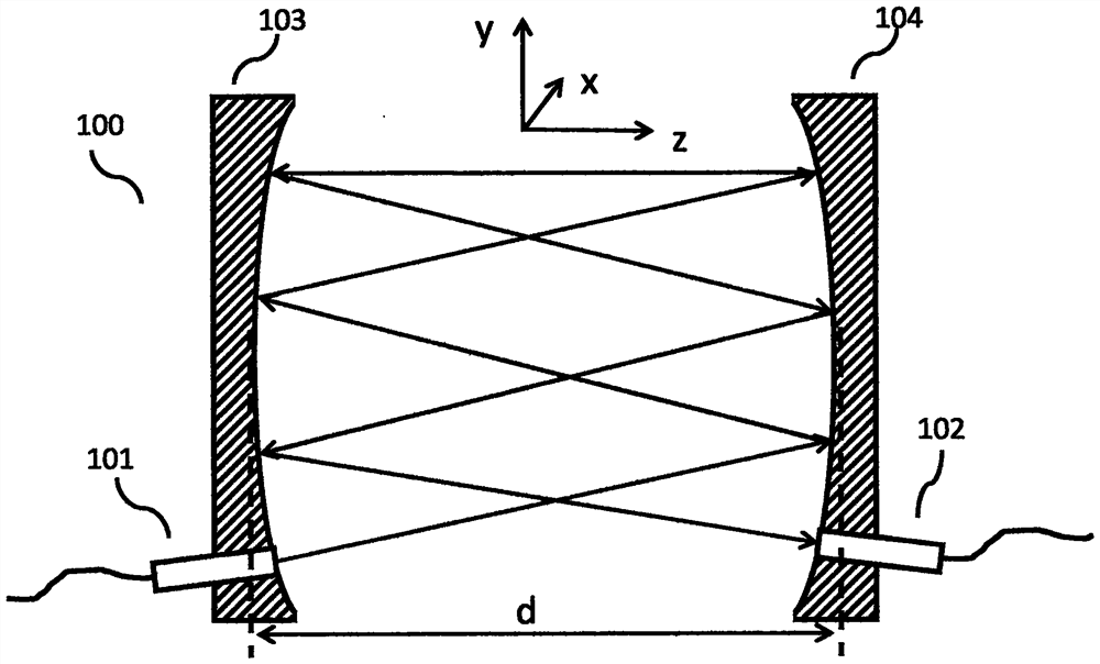
[0007] With the improvement of the industry's requirements for gas detection accuracy, the requirements for optical path gas chambers have also been further improved. It is necessary to achieve a longer optical path (more than 20 meters, or even more than 100 meters) in a limited volume. The Herriott chamber and White Chamber are difficult to achieve more reflections in a certain volume
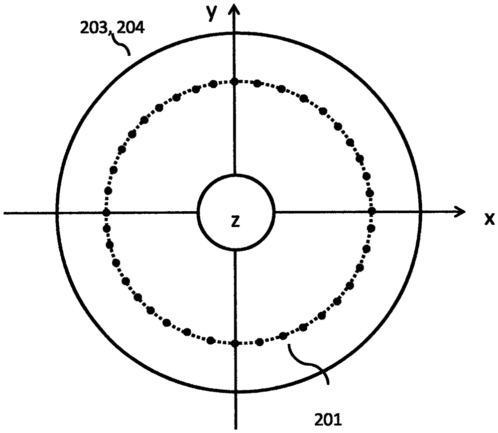
There are many improved designs based on the Heriott chamber and the White chamber, such as the astigmatic lens proposed by Heriot himself to achieve more reflections ("Folded Optical Delay Lines", Appl.Opt., Vol.4, No.8, pp883-889, 1965), but there is a problem that the astigmatism lens is difficult to process, although there is a follow-up to reduce the machining accuracy requirements by rotating an astigmatism lens (US Patent 5291265, 1994), the astigmatism lens is still not solved High processing cost; Joel.A.Silver et al. proposed to use double cylinder mirrors to achieve dense spot distribution, that is, more reflections (US Patent 7477377, 2009), but due to the non-rotational symmetry of the double cylinders, the beam After multiple reflections, it no longer has the same beam characteristics as the input beam, and cannot be applied in application scenarios that require the maintenance of beam characteristics (beam radius, divergence half angle, etc.)
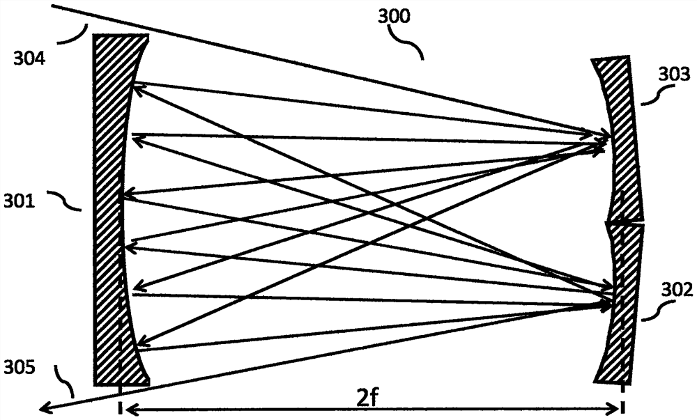
Although there are also some improved schemes based on the White chamber, such as the Chinese patent "folded multiple light path multi-pass gas cell" (CN102053063B), a corner reflector is used at the output end of the White chamber to reflect the output beam so that it returns along the original path (deviating from one small angle), the optical path is doubled, but the input and output ends are too close, requiring more space to separate the input and output beams; at the same time, the White chamber uses an angled secondary mirror, and after the beam is reflected many times, the aberration has no effect on the output The influence of the beam characteristics is large

Method used


Image

  • An optical path folding device
  • An optical path folding device
  • An optical path folding device

Examples


Embodiment 1

[0054] like Figure 10 As shown, an optical path folding device (1000) provided by the present invention includes:

[0055] An input port (1001) for inputting a light beam;

[0056] an output port (1002), for outputting light beams;

[0057] a principal plane mirror (1004);

[0058]A concave reflector (1003) has a focal plane (1006), and the distance (1007) from the focal plane to the concave reflector is the focal length f of the concave reflector; the focal plane also has an origin (1009), which is The intersection point of the optical axis (1008) of the optical system composed of the main plane reflector and the concave reflector.

[0059] A tilting sub-mirror (1005), which is a facet mirror whose normal line forms an inclination angle θ with the normal line of the main plane mirror;

[0060] The input end, the output end, the main plane reflector, and the inclined sub-reflector are coplanar and located on the focal plane of the concave reflector; the light beam is inpu...

Embodiment 2

[0065] This embodiment is similar to embodiment 1, as Figure 11 As shown, the difference with embodiment 1 is:

[0066] 1. The input end (1101) and the output end (1102) are fiber collimators with pigtails, the input beam is coherent light, and the beam input from the fiber collimator to the optical path folding device is a Gaussian beam, which has a Gaussian beam The waist radius ω and the far-field divergence half-angle α define the beam radius as A 0 =3ω, divergence half angle β 0 =3α, to cover most of the energy of the Gaussian beam, and thus obtain the distance that the tilted sub-reflector (1105) deviates from the origin (1109) is 6α f, and the aperture is taken as 9α f; the edge distance input of the tilted sub-reflector and The shortest distance of the connecting line at the output end is taken as 6ω.

[0067] 2. The concave reflector (1103) is a spherical reflector.

[0068] In the case of ω=0.2mm, f=200mm, and α=2.5mrad, it can be obtained that the distance of t...

Embodiment 3

[0070] This embodiment is similar to Embodiment 2, as Figure 12 As shown, the difference is that the tilting sub-mirror (1205) can be rotated along the tilting direction to change the size of the tilting angle θ, and its rotation axis (1218) is within the focal plane (1206) where the main plane mirror (1204) is located , and driven by a piezoelectric ceramic driver (1219), the tilt angle θ is measured by an optical angle measuring device (1220) with a measuring laser and a four-quadrant detector. After reflection, it reaches the four-quadrant detector, and the size and direction of the inclination angle θ are obtained after comparison and calculation of the light intensity data of the four-quadrant detector.

[0071] The variable tilt angle θ leads to variable displacement vector ΔP, and the selection of the tilt angle θ makes the distance between the input end and the output end an integer multiple of ΔP, so that the light beam can reach the output end (1202) from the input ...


PUM


Abstract

The invention provides an optical path folding device. On the basis of the confocal optical system composed of the beam input end, the output end, the main plane reflector and the concave reflector, an inclined sub-reflector is introduced on the focal plane to change the incident The reflection angle of the beam on it can realize multiple reflections of the beam in the confocal optical system; the output beam can maintain the optical characteristics of the input beam, and has a higher optical path volume ratio; by rotating the tilting sub-mirror, it can realize Variable optical path; the parallel input of multiple beams can be realized by adopting the fiber array collimator at the input end; the fiber array collimator is used at the input and output ends, and some pigtail fibers are connected to realize the series connection of the optical path. Achieve longer optical path length.

Description

technical field [0001] The invention relates to an optical path folding device in the field of optical sensing, in particular to an optical path folding device used for gas optical sensing and variable optical path. Background technique [0002] In a limited volume, multiple reflections of the light beam are realized, so that the light beam travels through a relatively long optical path. Such optical devices have important applications in the field of optical sensing, especially for the sensing and analysis of special gases. [0003] At present, semiconductor tunable laser absorption spectroscopy (hereinafter referred to as TDLAS) and Fourier transform infrared spectroscopy (hereinafter referred to as FTIR) are two mainstream technical routes. The former is mainly based on tunable laser for spectral analysis in the near-infrared band, and the latter Spectral analysis was performed in the mid-to-far infrared by Fourier transform using a broad-spectrum light source. [0004] ...

Claims


Application Information

Patent Timeline
Patent Type & Authority Patents(China)
IPC IPC(8): G02B17/06G01N21/39
CPCG01N21/39G02B17/0684G01N21/00G02B17/06
Inventor 陈波许辉杰温俊华
Owner XUZHOU XUHAI OPTO ELECTRONICS TECH CO LTD
Learn More