Broadband optical fiber amplifier

A fiber amplifier and broadband technology, applied in the optical field, can solve the problems affecting the output power of the amplifier and the conversion efficiency of the pump power, increase the insertion loss, and increase the cost of the amplifier, so as to improve the conversion efficiency of the pump power, reduce the output loss, and improve the optical device. less effect

Inactive Publication Date: 2006-08-09
HUAWEI TECH CO LTD
View PDF0 Cites 10 Cited by
  • Summary
  • Abstract
  • Description
  • Claims
  • Application Information

AI Technical Summary

Problems solved by technology

[0007] The optical path structure of the existing C+L band optical fiber amplifier determines that two sets of optical devices must be used. The more optical devices are used, the higher the cost of the amplifier, and the more optical devices are used, the more complicated the processing. Therefore, this The manufacturing cost of C+L band optical fiber amplifier with structure is

Method used


Image

  • Broadband optical fiber amplifier
  • Broadband optical fiber amplifier
  • Broadband optical fiber amplifier

Examples


Embodiment Construction

[0040] Below according to accompanying drawing and embodiment the present invention will be described in further detail:

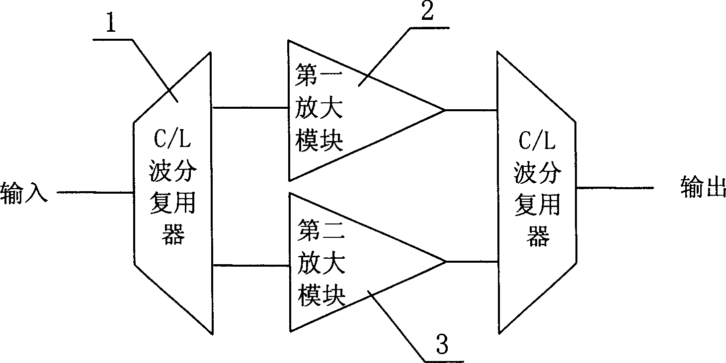
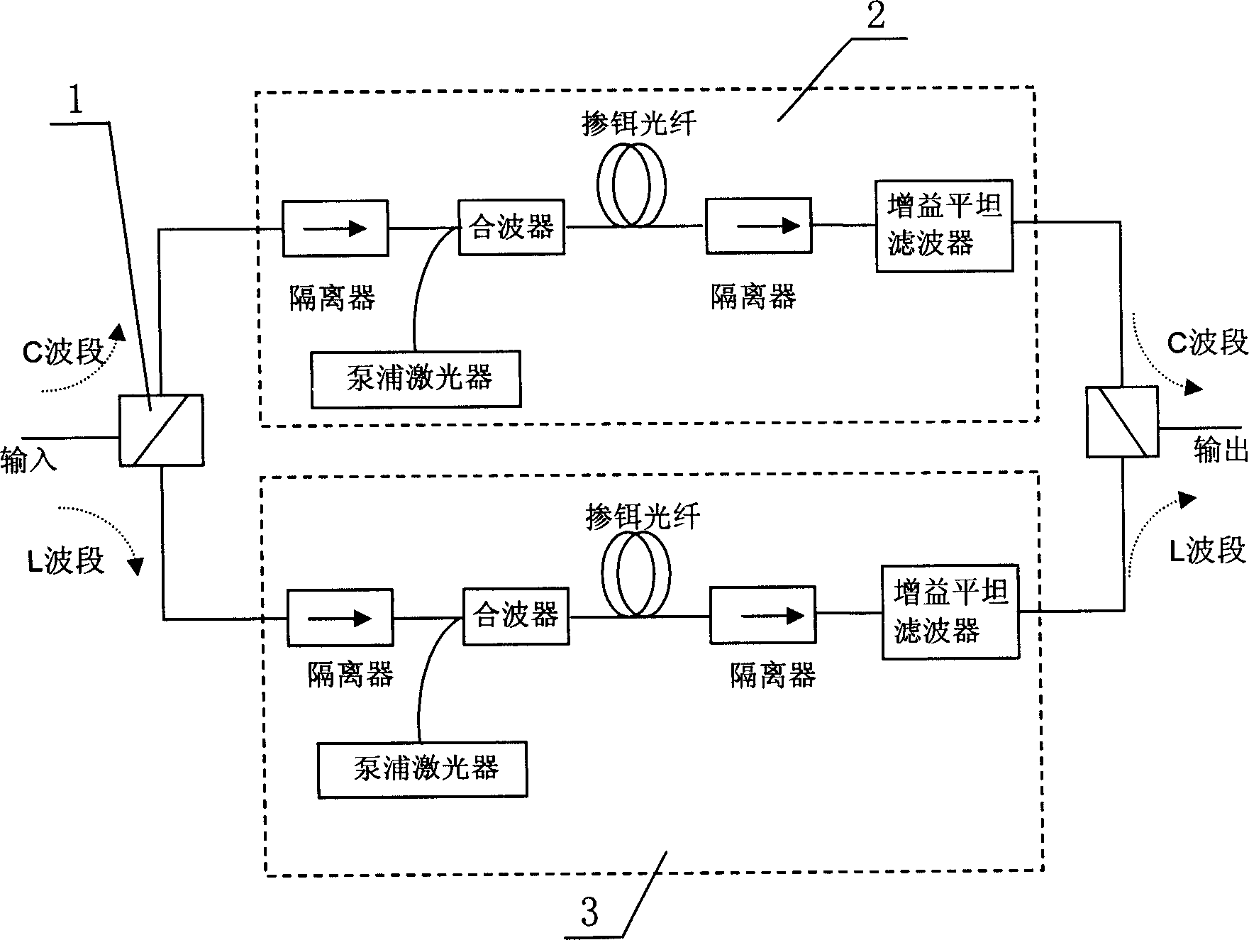
[0041] according to Figure 5 , the present invention includes a first amplifying module 2 and a second amplifying module 3, the first amplifying module 2 is used to amplify the signal power of the short wavelength band and the long wavelength band; the second amplifying module 3 is used for amplifying the signal power of the long wavelength band, for this In an embodiment, specifically, the short-wavelength band may refer to the C-band, and the long-wavelength band may refer to the L-band.

[0042] Such as Figure 5 As shown, the filter module 4 is connected in series between the output end of the first amplification module 2 and the input end of the second amplification module 3, the input end of the first amplification module 2 is connected to the circulator 6, and the port 2 of the circulator 6 is connected to the first amplification module 2 The inp...


PUM


Abstract

The optical fiber amplifier includes first amplification (Amp) module and second Amp module. Characters are that filtering module is cascaded between output end of first Amp module and input end of the second Amp module; input end of first Amp module is connected to circulator, and output end of second Amp module is connected to a reflection module; the filtering module generates actions of reflection and transmission respectively for signal lights in shot wavelength band and long wavelength band; reflection module reflects signal light in long wavelength band; a port of the circulator is connected to the input end of the first Amp module; other two ports of the circulator are use for receiving and outputting signal light; first Amp module is in use for magnifying powers of signal in shot wavelength band and long wavelength band, and second Amp module is in use for magnifying power of signal in long wavelength band. Features are: simple structure, low cost, high efficiency.

Description

technical field [0001] The invention relates to optics, in particular to a broadband optical fiber amplifier. Background technique [0002] Wavelength division multiplexing technology refers to the communication technology that transmits optical signals of multiple wavelengths in the same optical fiber, such as figure 1 The schematic diagram of a typical structure of a wavelength division multiplexing communication system is shown. The transmitting modules TX1, TX2, TX3...TXn respectively send out signal lights with wavelengths of λ1, λ2, λ3...λn, and the signal lights of different wavelengths pass through a wavelength division multiplexing Coupled to the same optical fiber for propagation, then the signal light is input into the fiber amplifier, the power of the signal light is amplified and increased, and the signal light is amplified and then propagates in the transmission fiber. Due to the loss characteristics of the transmission fiber, the signal propagating in the tran...

Claims


Application Information

Patent Timeline
IPC IPC(8): G02F1/39G02F1/35H04J14/02
Inventor 张文斗马立苹
Owner HUAWEI TECH CO LTD
Why Eureka
Try Eureka