Dry isolation transformer

An isolation transformer and dry-type technology, applied in the direction of transformers, fixed transformers, transformer/inductor cores, etc., can solve the problems of main insulation distance, dry arc distance, insufficient creepage distance, poor insulation withstand voltage, etc., to achieve High energy transfer efficiency, improved insulation withstand voltage capability, and increased main insulation distance

Pending Publication Date: 2019-01-15
SUZHOU KANGKAI ELECTRIC
View PDF0 Cites 0 Cited by
  • Summary
  • Abstract
  • Description
  • Claims
  • Application Information

AI Technical Summary

Problems solved by technology

[0002] Existing transformers usually adopt the structure in which the input coil and output coil are installed on the same core column, and there ar

Method used


Image

  • Dry isolation transformer
  • Dry isolation transformer
  • Dry isolation transformer

Examples


Example Embodiment

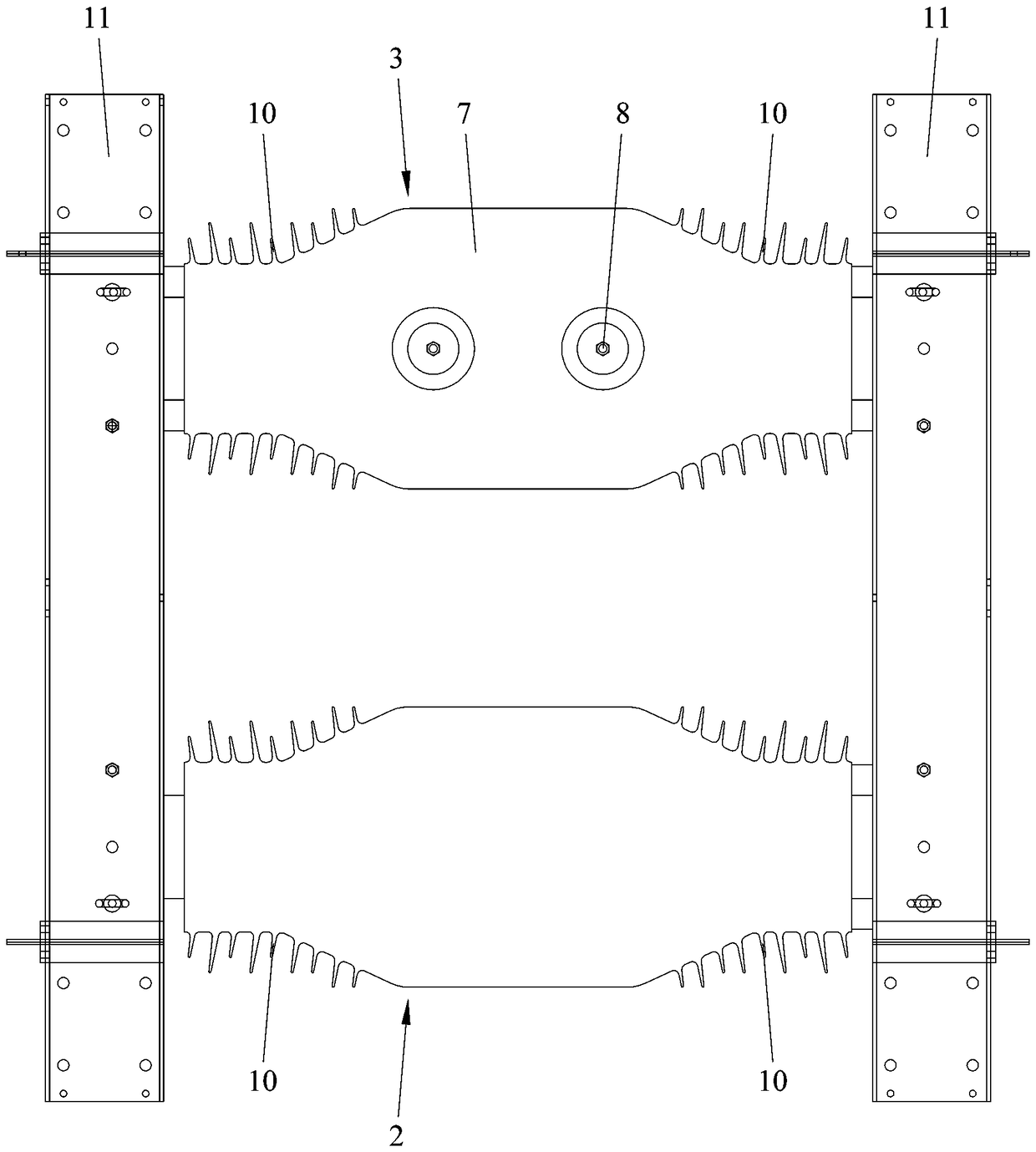
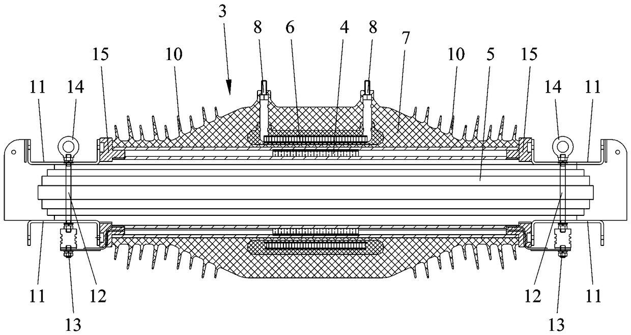
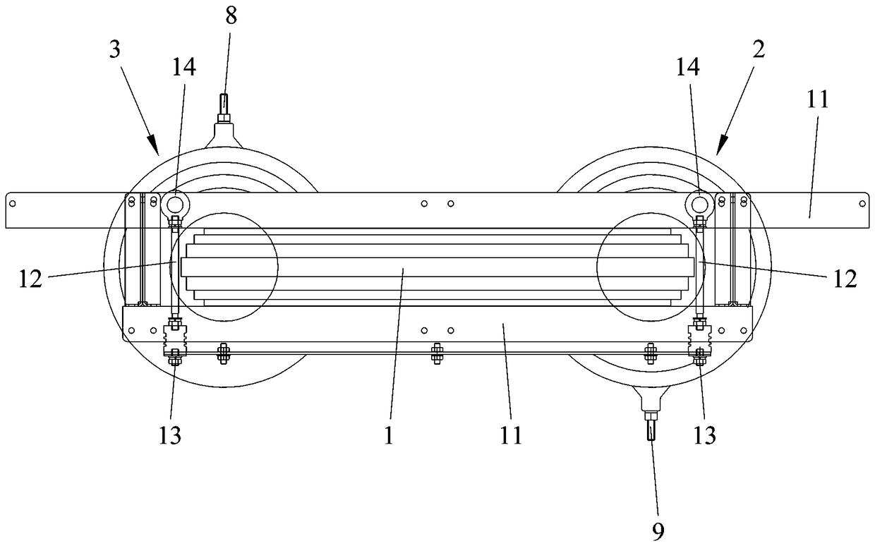
[0022] Embodiment one: as attached figure 1 To attach image 3 As shown, a dry-type isolation transformer includes a core 1 , an input winding 2 , an output winding 3 , and an intermediate winding 4 .

[0023] The iron core 1 includes two separate and connected iron core legs, respectively referred to as a first iron core leg and a second iron core leg 5 , and the iron core legs have an axis. The intermediate winding 4 for transferring energy includes a first part N1' and a second part N2', and the two ends of the two parts are correspondingly connected to form a loop. The first part N1' of the intermediate winding 4 and the input winding 2 are arranged on a core leg, that is, the first core leg, the first part N1' of the intermediate winding 4 is wound in the middle of the first core leg, and the input winding 2 is arranged on the The first part N1' of the intermediate winding 4 and the outer circumference of the first core leg where it is located. The second part N2' of t...


PUM


Abstract

A dry isolation transformer including the core, Input winding, an output winding, the iron core comprising two iron core columns, the dry isolation transformer further comprising an intermediate winding for transmitting energy, the intermediate winding comprising a connected first portion and a second portion, the first portion of the intermediate winding and the input winding being arranged on one iron core column, the second portion of the winding and the output winding being arranged on the other iron core column; The input winding comprises an input coil and an input insulator poured by silicone rubber on the outer periphery of the input coil. The output winding comprises an output coil, an output insulator cast on the outer periphery of the output coil by silicone rubber; A pluralityof umbrella skirts are formed on the input insulator/output insulator at both ends of the input coil/at both ends of the output coil. The invention can effectively increase the main insulation distance, the dry arc distance and the creepage distance of the input winding and the output winding, further improve the insulation withstand voltage ability of the transformer, and has the advantages of high energy transfer efficiency, environmental protection and high efficiency.

Description

technical field [0001] The invention belongs to the field of electrical equipment, and in particular relates to a dry-type isolation transformer. Background technique [0002] Existing transformers usually adopt a structure in which the input coil and the output coil are installed on the same core column, which generally has problems of insufficient main insulation distance, dry arc distance, and creepage distance, and poor insulation withstand voltage capability. Contents of the invention [0003] The purpose of the present invention is to provide a dry-type isolation transformer that can effectively improve the main insulation distance, dry arc distance and creepage distance, and improve the insulation withstand voltage capability. [0004] In order to achieve the above object, the technical scheme adopted in the present invention is: [0005] A dry-type isolation transformer includes an iron core, an input winding, and an output winding. The iron core includes two iron...

Claims


Application Information

Patent Timeline
IPC IPC(8): H01F30/06H01F27/32H01F27/28H01F27/26H01F27/24
CPCH01F27/245H01F27/263H01F27/28H01F27/324H01F30/06
Inventor 沈永福
Owner SUZHOU KANGKAI ELECTRIC
Why Eureka
Try Eureka