
Sounder

A sound generator and rear sound hole technology, applied in the direction of sensors, loudspeakers, sensor components, etc., can solve the problems of irregular shape of the rear cavity, polarization, and insufficient airflow stability, so as to simplify the manufacturing process and installation process, and ensure Acoustic performance, the effect of improving production efficiency

Pending Publication Date: 2019-01-15
GOERTEK INC
View PDF0 Cites 2 Cited by
  • Summary
  • Abstract
  • Description
  • Claims
  • Application Information

AI Technical Summary

Problems solved by technology

The sounding device of the prior art usually has two structures: one is a structure similar to a sound box, the box body is a cuboid shape, and the sounder is fixed on the front panel of the box body, forming a rear cavity in the thickness direction and the rear horizontal direction. , which is not conducive to the thinning and miniaturization of the product; another structure is that the box has a receiving cavity for the sounder and a rear cavity on the side of the sounder, and forming the rear cavity on the side of the sounder can obtain the largest possible The volume of the rear cavity, but at the same time it also leads to a large space occupied by the entire sounding device in the horizontal direction, which is not conducive to the miniaturization of the product
[0004] Moreover, the shape of the back cavity of the sound generating device in the prior art is irregular, and the airflow entering the back cavity from the sound generator is not stable enough, which easily causes problems such as polarization and distortion, and the acoustic effect is not ideal.

Method used


Image

  • Sounder
  • Sounder
  • Sounder

Examples


Embodiment Construction

[0055] Various exemplary embodiments of the present invention will now be described in detail with reference to the accompanying drawings. It should be noted that the relative arrangements of components and steps, numerical expressions and numerical values ​​set forth in these embodiments do not limit the scope of the present invention unless specifically stated otherwise. The following description of at least one exemplary embodiment is merely illustrative in nature and in no way taken as limiting the invention, its application or uses.

[0056] Techniques and devices known to those of ordinary skill in the relevant art may not be discussed in detail, but where appropriate, such techniques and devices should be considered part of the description. In all examples shown and discussed herein, any specific values ​​should be construed as exemplary only, and not as limitations. Therefore, other instances of the exemplary embodiment may have different values. It should be noted t...


PUM


Abstract

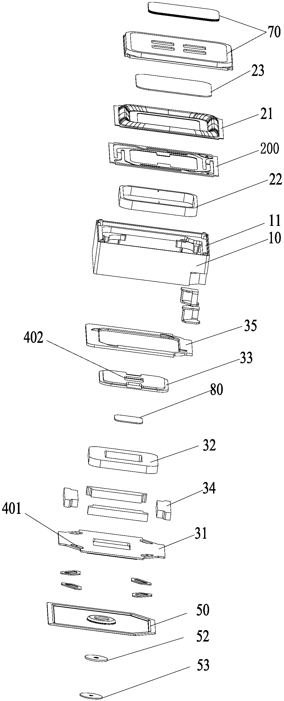
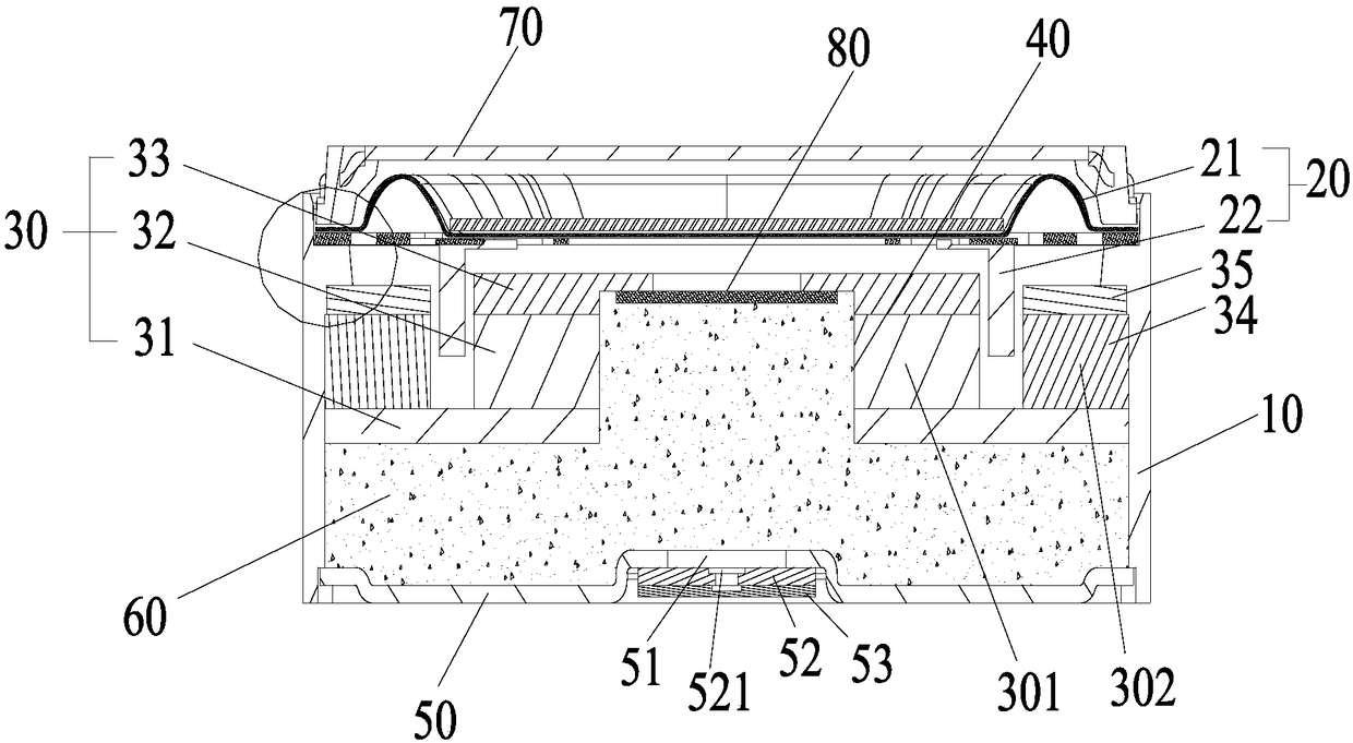
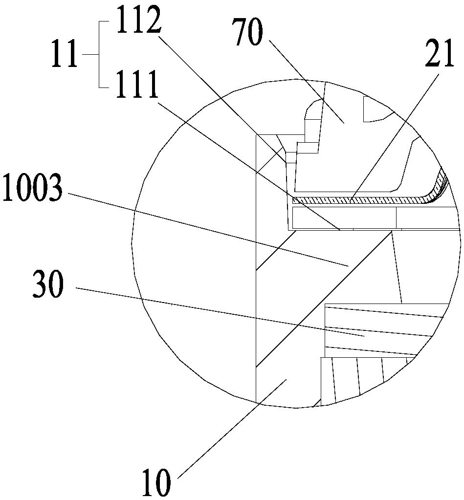
The embodiment of the present invention provides a sounder including a housing, a vibration system, and a magnetic circuit system. The first end of the housing successively houses and fixes the vibration system and the magnetic circuit system from top to bottom. A rear sound hole is disposed on the magnetic circuit system. The housing includes a first portion corresponding to the vibration systemand the magnetic circuit system, and a second portion extending integrally downward from the first portion beyond the bottom surface of the magnetic circuit system. On the end portion of the second end of the housing, a housing bottom wall is integrally disposed or a lower cover plate is mounted in a split manner. A rear cavity communicating with the rear sound hole is formed among the second portion of the housing, the bottom surface of the magnetic circuit system and the housing bottom wall or the lower cover plate. The technical solution provided by the present invention contributes to miniaturization of a product.

Description

technical field [0001] The invention relates to the technical field of sound generating devices. Background technique [0002] The sound generating device is an important component in electronic products, which is used to convert electrical signals into acoustic signals. The development trend of electronic products is getting thinner and thinner, and in order to achieve more functions, there are more and more components in electronic products, and the space reserved for sound generating devices is bound to become smaller and smaller, and electronic products pay more and more attention to The user's music experience is therefore required to have better sound quality from the sound generating device. [0003] In order to improve the music experience effect, the sounding device in the prior art installs the sounder in a box with a volume, the sounder includes a housing and a magnetic circuit system and a vibration system accommodated and fixed in the housing, the sounder and t...

Claims


Application Information

Patent Timeline
IPC IPC(8): H04R9/06H04R9/02
CPCH04R9/025H04R9/06H04R2400/11H04R1/2811H04R7/04
Inventor 赵国栋郑泽东李培俊姬雅倩
Owner GOERTEK INC
Learn More