Pipe bending machine

A pipe bending machine and pipe bending technology, which is applied in the field of pipe bending machines, can solve the problems of manual adjustment, breakage, and poor quality of pipe fittings, and achieve the effects of increasing pipe bending resistance, convenient use, and improving pipe bending quality

Active Publication Date: 2019-01-18
YANG ZHOU MEIHUA ELECTRIC CO LTD
View PDF8 Cites 1 Cited by
  • Summary
  • Abstract
  • Description
  • Claims
  • Application Information

AI Technical Summary

Problems solved by technology

Although the existing technology can prevent the flat deformation of the bending section when the straight pipe to be bent is bent, which improves the bending efficiency of the pipe; The inside of the pipe plays a role of supporting the inside of the straight pipe wall to be bent, balances the shear stress, eliminates shear yield, and avoids normal plastic dislocation, so that the flattening of the bent section will not occur when the straight pipe to be bent is bent However, since the universal ball head only swings according to the bending of the pipe, the outer arc of the elbow will be thinned when bending a small arc bend. When the outer arc is too thin, it is easy to break and the quality of the pipe is not good. High, at the same time, after the end of the bend, you need to manually adjust the universal joint for the next use

Method used


Image

  • Pipe bending machine
  • Pipe bending machine
  • Pipe bending machine

Examples


Embodiment Construction

[0026] Below in conjunction with specific embodiment, further illustrate the present invention, it should be understood that these embodiments are only used to illustrate the present invention and are not intended to limit the scope of the present invention, after reading the present invention, those skilled in the art will understand the various equivalent forms of the present invention All modifications fall within the scope defined by the appended claims of the present application.

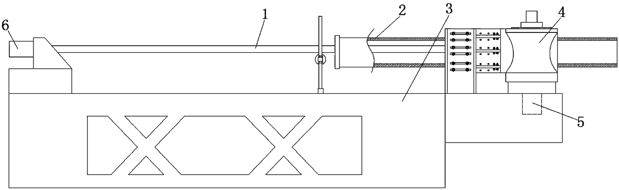
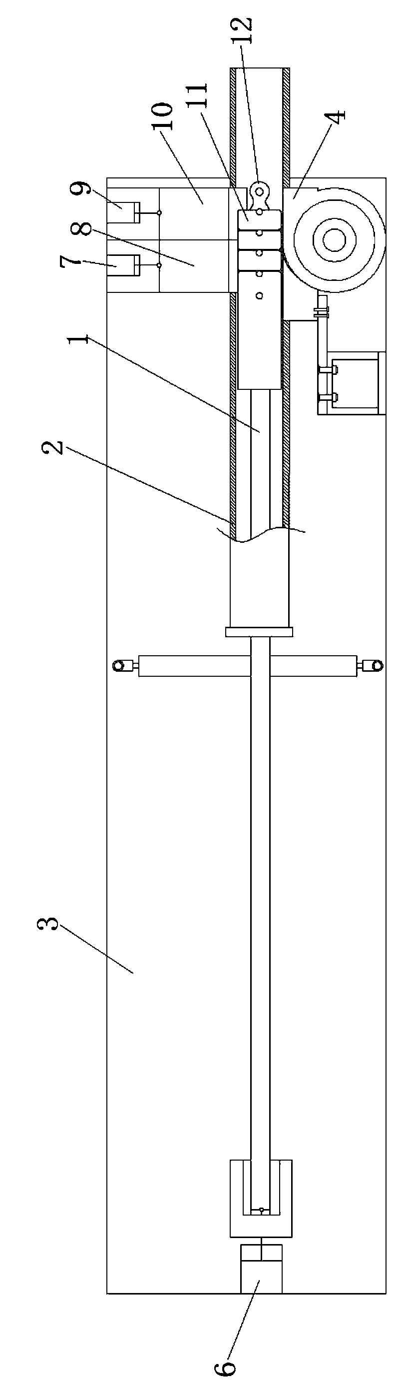
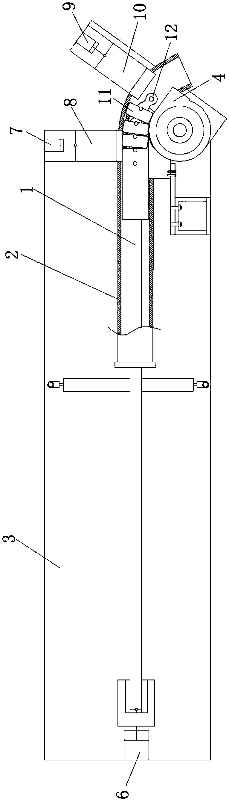
[0027] Such as Figure 1-9 As shown, a pipe bending machine includes a workbench 3, a feed mechanism arranged on the workbench 3, a pressing mechanism for pressing the pipe material 2, and a pipe bending mechanism for bending the pipe material 2. The mechanism includes a mandrel 1 set on the workbench 3 and set in the pipe 2, and also includes a rotating device for driving the pipe 2 to bend. The feed cylinder 6 and the cylinder barrel of the feed cylinder 6 are fixed on the workbench 3, the p...


PUM


Abstract

The invention discloses a pipe bending machine in the field of mechanical manufacturing. The pipe bending machine comprises a work table, a feeding mechanism, a pressing mechanism and a pipe bending mechanism, wherein the feeding mechanism is arranged on the work table, the pressing mechanism is used for pressing a pipe material, and the pipe bending mechanism is used for bending the pipe material; the pipe bending mechanism comprises a core rod sleeved with the pipe material on the work table, and further comprises a rotating device driving the pipe material to bend, one end of the core rod is connected with the feeding mechanism, the other end of the core rod is provided with a bent pipe head capable of being bent, the bent pipe head comprises a plurality of bent pipe pieces which are connected with one another, and the center of the bent pipe pieces are provided with openings; the outer sides of the openings of the bent pipe pieces are provided with arc-shaped grooves, and an elastic member and a limiting member used for limiting the expansion and contraction of the elastic member are arranged between every adjacent two bent pipe pieces; the elastic members comprise arc-shaped plates matched with the arc-shaped grooves, the arc-shaped plates are provided with a plurality of telescopic springs, one end of each telescopic spring is connected to the arc-shaped plate of one of the bent pipe pieces, and the other end of the corresponding telescopic spring is connected to the arc-shaped plate of the adjacent bent pipe piece. The pipe bending machine has the advantages that theuse is convenient and the pipe bending quality is improved.

Description

technical field [0001] The invention relates to the field of mechanical manufacturing, in particular to a pipe bending machine. Background technique [0002] In the existing cold-state pipe bending technology, the rotary pipe bender can bend pipes of various specifications. However, because the pipe is a hollow part, when the pipe is bent, the stress on the bent part is complicated, and it is prone to wrinkles or cross-section changes. Oval, the quality of the bent pipe is difficult to control, especially when bending a small arc bend, the stress on the pipe is concentrated, and it is particularly easy to cause deformation at the bend of the pipe when bending the pipe. Therefore, an invention is disclosed in the prior art, the application number is CN201721646512.0, the authorized announcement number is CN207592509U, and the authorized announcement date is 20180710. body, the mandrel also includes a plurality of universal ball joints hinged in sequence, one end of the unive...

Claims


Application Information

Patent Timeline
Patent Type & Authority Applications(China)
IPC IPC(8): B21D9/03B21D9/16
CPCB21D9/03B21D9/16
Inventor 胡春勇汤永锋
Owner YANG ZHOU MEIHUA ELECTRIC CO LTD
Why Eureka
Try Eureka