Mechanical part precise grooving device

A precise technology for mechanical parts, applied in the field of precise slotting devices for mechanical parts, can solve problems such as the inability to accurately control the slotting depth, achieve the effects of improving slotting efficiency and slotting accuracy, simple structure, and strong practicability

Inactive Publication Date: 2019-01-18
HENAN HUANQIU AVIATION EQUIP TECH CO LTD
View PDF6 Cites 3 Cited by
  • Summary
  • Abstract
  • Description
  • Claims
  • Application Information

AI Technical Summary

Problems solved by technology

However, this kind of slotting machine does not solve the technical problem that the slotting depth cannot be precisely controlled, and can only be operated by the worker's experience and feel

Method used


Image

  • Mechanical part precise grooving device
  • Mechanical part precise grooving device
  • Mechanical part precise grooving device

Examples


Embodiment 1

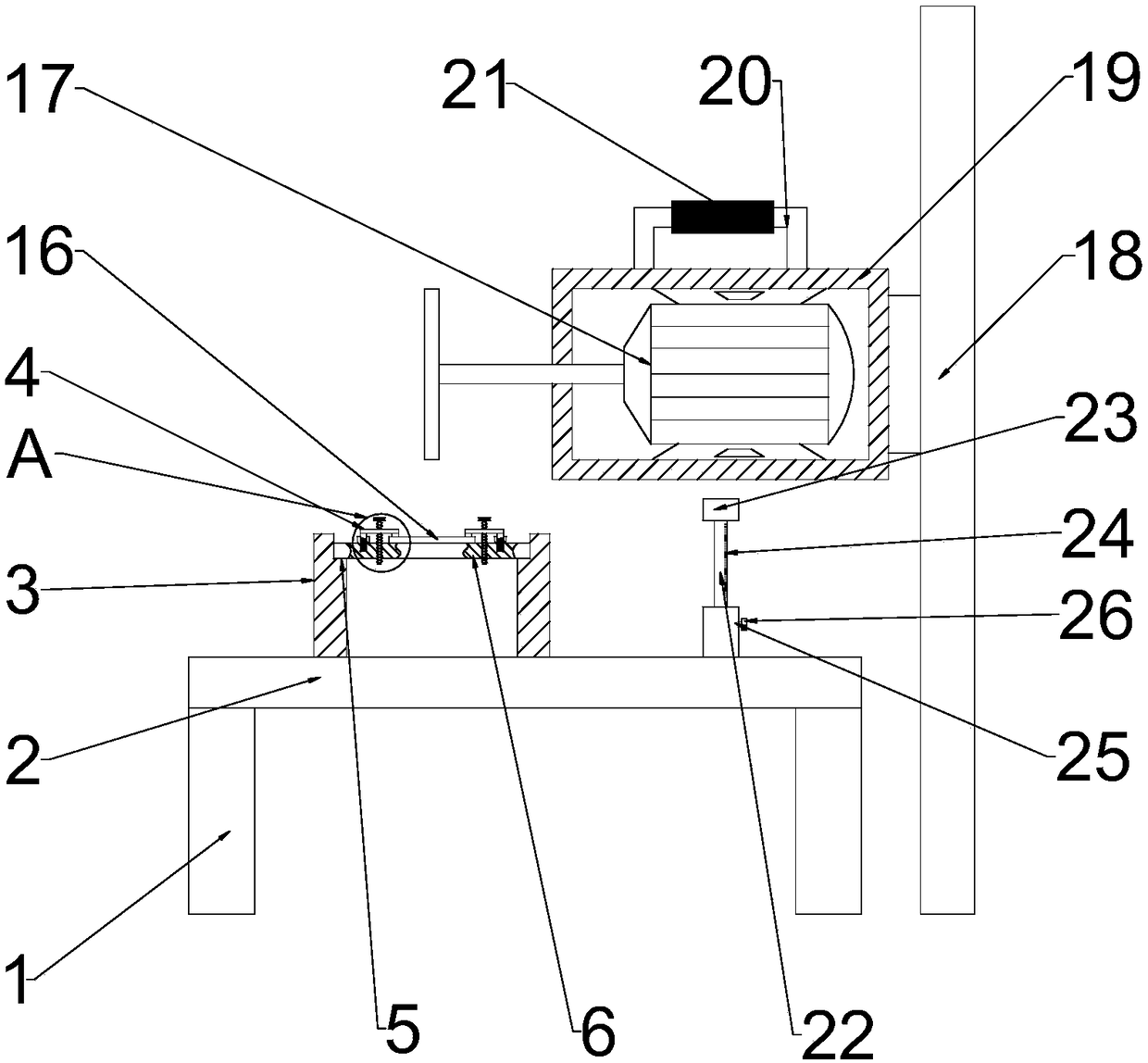
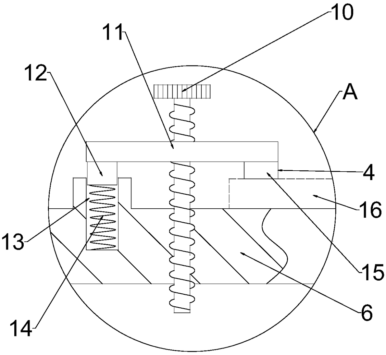
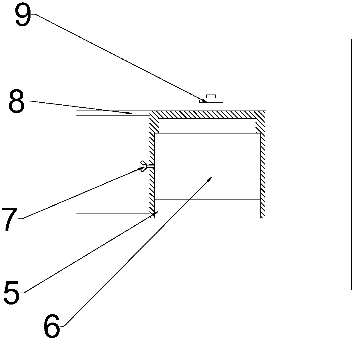
[0016] see figure 1 , figure 2 and image 3 , a precise slotting device for mechanical parts, including a frame 1, a desktop 2, a part 16 and a slotting machine 17, the frame 1 is welded and fixed on the bottom of the desktop 2, and the part 16 is fixed above the desktop 2, The slotting machine 17 is arranged above the part 16; the left and right chute 8 is processed on the upper surface of the desktop 2, and the fixed barrel 3 is slidably installed in the left and right chute 8, and the fixed barrel 3 is provided with The left and right fixing bolts 9 can adjust the position of the fixed barrel 3 in the left and right chutes 8 and fix the left and right chutes 8; the front and rear chutes 5 are processed on the fixed barrel 3, and the front and rear chutes 5 are The front and rear sliders 6 are slidingly installed, and the front and rear sliders 6 are fixed by the front and rear fixing bolts 7, so that the front and rear sliders 6 can slide and be fixed on the fixed bucket...

Embodiment 2

[0018] see Figure 4 , compared with Embodiment 1, the difference between Embodiment 2 and Embodiment 1 is that a buffer mechanism 27 is symmetrically arranged on the left and right sides of the bottom of the installation bucket 19, which plays a good buffer role and is used to protect the limit mechanism 22; the buffer mechanism 27 includes a casing 28, a buffer block 29 and a spring 30, the top of the casing 28 is close to the bottom of the installation bucket 19, the inner cavity of the spring 30 is slidably installed below the casing 28 and the bottom is tightly connected to the buffer block 29 paste.

[0019] The working principle of the present invention is: through described front and rear chute 5 and described left and right chute 8 can adjust the relative position of described parts 16 and described slotting machine 17, when described slotting machine 17 is positioned at described parts 16 For the position where slotting is required, the position of the part 16 is fi...


PUM


Abstract

The invention relates to the technical field of machining, in particular to a mechanical part precise grooving device which comprises a frame, a tabletop, a part and a grooving machine. A left slide groove and a right slide groove are machined in the upper end face of the tabletop. A fixed barrel is left-right slidingly installed in the left slide groove and the right slide groove and provided with a left fixing bolt and a right fixing bolt. A front slide groove and a rear slide groove are machined in the fixed barrel. A front slider and a rear slider are front-back slidingly installed in thefront slide groove and the rear slide groove. The front slider and the rear slider are fixed by the front fixing bolt and the rear fixing bolt. The part is fixed to the upper end face of the front slider and the upper end face of the rear slider through workpiece fastening mechanisms. The outer side of the grooving machine is sleeved with an installation barrel. The right side face of the installation barrel is vertically slidingly installed on a stand column. A limiting mechanism is arranged at the lower portion of the installation barrel. The mechanical part precise grooving device is simplein structure, low in cost, suitable for machining grooves with various shapes and extremely wide in application range, can precisely control the grooving depth and greatly improve the grooving efficiency and grooving precision, and has great significance in improving economic benefits for enterprises.

Description

technical field [0001] The invention relates to the technical field of machining, in particular to a precision slotting device for mechanical parts. Background technique [0002] Slotting is one of the common rework processes in the process of parts rework. Usually, workers use slotting knives to notch parts, but the precision of the grooves made in this way is low and not beautiful enough. [0003] Chinese patent (notification number: CN203779623U, announcement date: 2014.08.20) discloses a slotting machine, including a worktable and a slotting mechanism, the worktable is installed on a horizontal guide rail, and the horizontal guide rail is installed on the base; There is a support beam on which a cylinder is installed, and the lower part of the cylinder passes through the support beam to connect with the pressure beam; the slotting mechanism includes a motor and a slotting knife connected with the motor, and the motor and the slotting knife are installed on the pneumatic ...

Claims


Application Information

Patent Timeline
Patent Type & Authority Applications(China)
IPC IPC(8): B23D79/00B23Q3/06B23Q1/25
CPCB23D79/00B23Q1/25B23Q3/06
Inventor 王飞
Owner HENAN HUANQIU AVIATION EQUIP TECH CO LTD
Why Eureka
Try Eureka