Numerical control groove punching machine and groove punching method thereof

A grooving machine and grooving technology, applied in the field of stamping processing, can solve the problems of slow grooving speed, inability to precisely control the grooving depth, and high production cost of the grooving machine, and achieve simple structure, high working reliability, and grooving. The effect of deep precise control

Inactive Publication Date: 2015-03-25
王洪辉
View PDF1 Cites 3 Cited by
  • Summary
  • Abstract
  • Description
  • Claims
  • Application Information

AI Technical Summary

Problems solved by technology

[0003] The purpose of the present invention is to provide a low production cost, fast slotting speed and precise control of the slotting depth to solve the problems of high production cost, slow slotting speed and inability to accurately control the slotting depth of the slotting machine in the prior art. CNC grooving machine and its grooving method

Method used


Image

  • Numerical control groove punching machine and groove punching method thereof
  • Numerical control groove punching machine and groove punching method thereof
  • Numerical control groove punching machine and groove punching method thereof

Examples


Embodiment 1

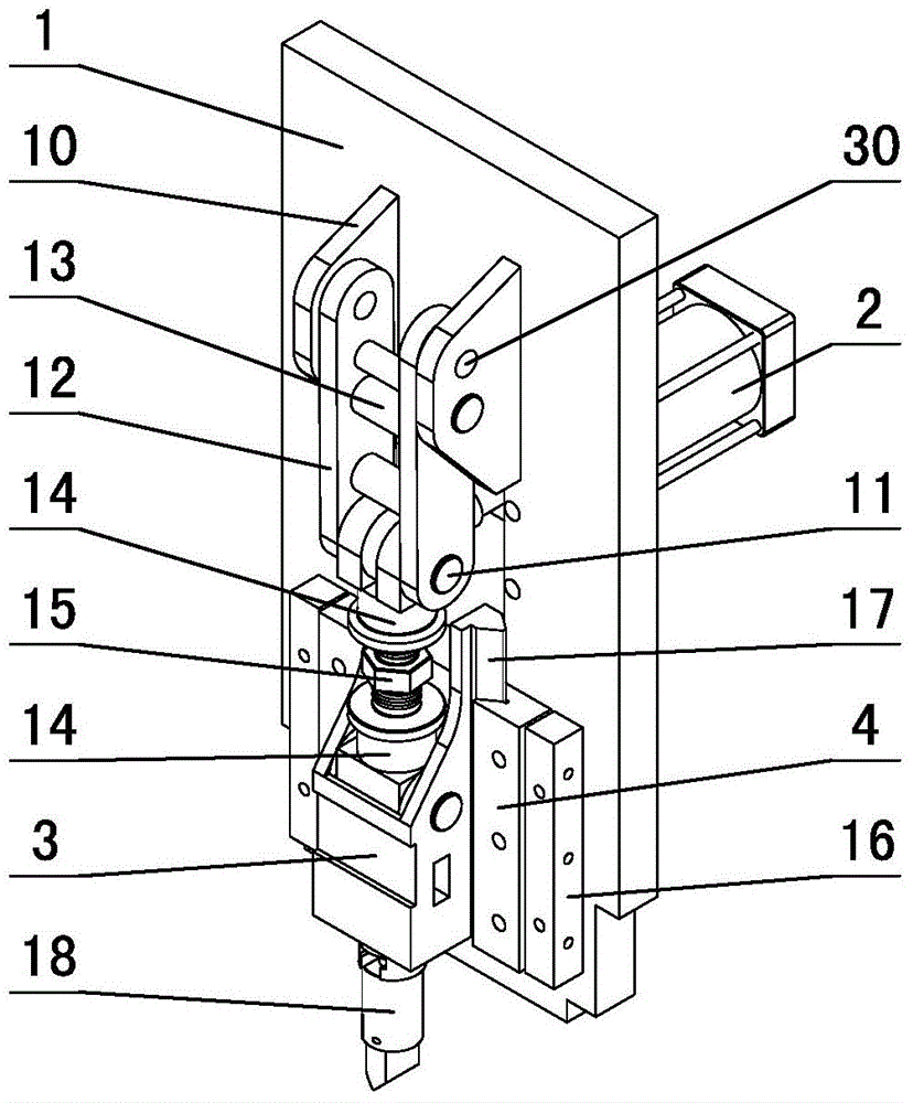
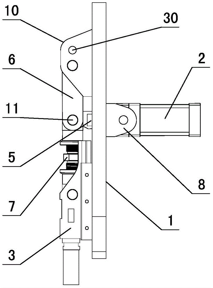
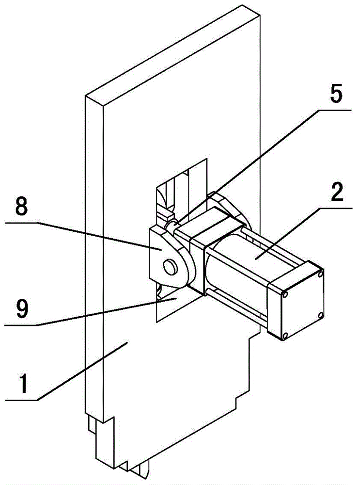
[0040] in such as figure 1 figure 2 image 3 In the shown embodiment 1, a kind of numerical control grooving machine comprises a frame (not shown in the figure) and a controller arranged on the frame, a numerically controlled feeding mechanism and a grooving mechanism, and the described NC grooving mechanism includes The base plate 1 and the double-acting cylinder 2 arranged on the base plate and the stamping block 3 used to drive the upper die of the grooving machine to work, the base plate is provided with a slide rail 4, the stamping block and the slide rail constitute a sliding pair, the cylinder of the cylinder The body is hinged on the base plate, and the piston rod 5 of the cylinder is connected with the stamping block through the booster frequency mechanism. The booster frequency mechanism includes an upper booster arm 6 and a lower booster arm 7. The arm is arranged on one side of the base plate, and the cylinder is hinged to the other side of the base plate throug...

Embodiment 2

[0052] exist Figure 4 Figure 5 In the shown embodiment 2, two grooving mechanisms are provided on the frame, and the two grooving mechanisms are arranged side by side in the moving direction of the feeding mechanism. The stamping block of the first grooving mechanism is provided with a V-shaped indenter 18 , the frame corresponding to the V-shaped indenter is provided with a columnar top block 19; the stamping block of the second groove mechanism is provided with a columnar indenter 20, and the frame corresponding to the columnar indenter is provided with a V-shaped top block 21 , all the other structures are the same as in Example 1.

[0053] The grooving method of the CNC grooving machine in this embodiment is to calculate the stamping positions of the upper surface and the lower surface of the slats that need to be grooved according to different character frame structures, and input them into the controller of the NC grooving machine, and the controller controls the firs...

Embodiment 3

[0055] exist Figure 6 In the shown embodiment 3, a die seat driven by a stepping motor is provided below the stamping block, and the die seat includes an upper die seat and a lower die seat, and several upper dies that can accommodate the upper die are arranged in the cylindrical upper die seat 22. Cavity 23, the upper mold cavity is arranged on the same circumferential surface with the center line of rotation of the mold base as the axis, the cross section of the upper mold cavity is circular, and the upper mold 24 can slide up and down in the upper mold cavity. An upper mold anti-rotation structure and an upper mold return spring are provided between the upper mold cavity; a number of positioning grooves 25 corresponding to the upper mold cavity are provided on the outer peripheral surface of the upper mold base, and a positioning groove 25 corresponding to the upper mold cavity is provided on the base plate. Scalable positioning plate 26, when the telescopic positioning pl...


PUM


Abstract

The invention discloses a numerical control groove punching machine and a groove punching method of the numerical control groove punching machine. The numerical control groove punching machine comprises a machine frame, a controller, a groove punching mechanism and a numerical control feeding mechanism, wherein the controller, the groove punching mechanism and the numerical control feeding mechanism are arranged on the machine frame. The numerical control groove punching mechanism comprises a base plate, a double-acting air cylinder and a punching block, wherein the double-acting air cylinder is arranged on the base plate, and the punching block is used for driving an upper die of the groove punching machine to work. A piston rod of the air cylinder is connected with the punching block through a boosting and frequency-increasing mechanism. The boosting and frequency-increasing mechanism comprises an upper boosting arm and a lower boosting arm. The upper end of the upper boosting arm is hinged to the base plate through a hinge base. The lower end of the upper boosting arm, the upper end of the lower boosting arm and the tail end of the piston rod are hinged through the same hinge shaft. The lower end of the lower boosting arm is hinged to the punching block. The numerical control groove punching machine and the groove punching method of the numerical control groove punching machine solve the problems that in the prior art, a grooving machine is high in production cost, low in grooving speed, and the groove depth consistency is poor. The numerical control groove punching machine is low in production cost, high in grooving speed, capable of accurately controlling the groove depth and conducting double-faced grooving, and high in practical value.

Description

technical field [0001] The invention relates to the technical field of stamping processing, in particular to a numerically controlled grooving machine with high precision, high speed and low cost and a grooving method thereof. Background technique [0002] In the field of advertising signboard production, it is necessary to slot horizontally on the strip-shaped metal sheet and bend it at the slot to form the frame of the hollow text. Since the thickness of the metal plate that constitutes the frame of the hollow text is usually small, so in The accuracy of the depth of the groove on the board is very high. The slotting methods of the traditional slotting machine are roughly divided into three types. The first method is to use a milling cutter to mill the slot. Its disadvantages are that the milling cutter is expensive and has a short service life, which is especially obvious when processing stainless steel. The second way is to use a planer for grooving. The disadvantage is...

Claims


Application Information

Patent Timeline
Patent Type & Authority Applications(China)
IPC IPC(8): B21D17/02B21D37/12
Inventor 王洪辉王洪良
Owner 王洪辉
Why Eureka
Try Eureka