Energy-saving material stacking and carrying device

A carrier device, energy-saving material technology, applied in the directions of transportation and packaging, multi-axis trolleys, trolley accessories, etc., can solve the problems of increased energy-saving glass breakage, no shock absorption device, increased use cost, etc., to achieve fast opening and convenient observation , the effect of long service life

Active Publication Date: 2019-01-18
诸暨市众创机械设备厂
View PDF7 Cites 5 Cited by
  • Summary
  • Abstract
  • Description
  • Claims
  • Application Information

AI Technical Summary

Problems solved by technology

[0002] With the popularization and promotion of the concept of energy saving, energy-saving materials have been widely used. As a new type of energy-saving material, energy-saving glass is widely used in the modern construction industry because of its advantages of safety, economy, lightness and environmental protection. When the glass is transported, it is usually stacked directly on the carrier. This method is not only inconvenient for loading and unloading, it is easy to cause scratches on the surface, affecting its aesthetics, and may cause damage to the bottom glass, which in turn will cause a decrease in the cost of use. In addition, most of the existing carrying devices are simple in structure and do not have shock absorbing devices. The vibration during transportation is relatively large, which further increases the probability of energy-saving glass breaking. In addition, most of the carrying devices can only transport a single type of glass, which is suitable for Smaller range, less practical

Method used


Image

  • Energy-saving material stacking and carrying device
  • Energy-saving material stacking and carrying device
  • Energy-saving material stacking and carrying device

Examples


Embodiment Construction

[0021] The following will clearly and completely describe the technical solutions in the embodiments of the present invention with reference to the accompanying drawings in the embodiments of the present invention. Obviously, the described embodiments are only some, not all, embodiments of the present invention. Based on the embodiments of the present invention, all other embodiments obtained by persons of ordinary skill in the art without making creative efforts belong to the protection scope of the present invention.

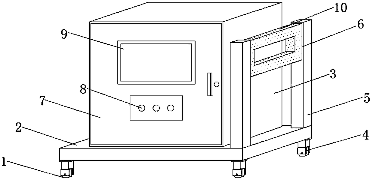
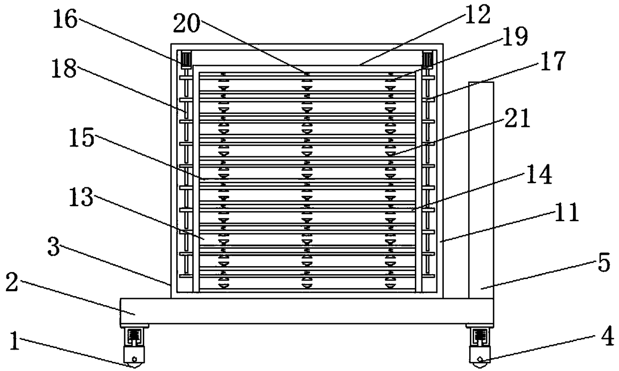
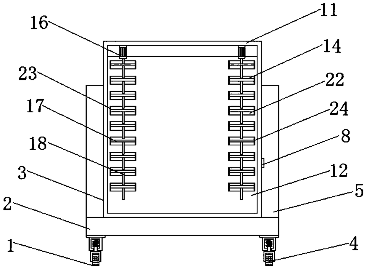
[0022] see Figure 1-5 , the present invention provides a technical solution: an energy-saving material stacking and carrying device, including a device body 1, a base 2, a carrying box 3, shock-absorbing casters 4, a pole 5, a folding push handle 6, a box door 7, and a control switch 8. Observation window 9, rubber layer 10, housing 11, placement chamber 12, accommodation groove 13, moving plate 14, fixed plate 15, electric push rod 16, convex plate 17, push ...


PUM


Abstract

An energy-saving material stacking and carrying device is disclosed. A base is arranged at the bottom of the device body, A carrier tank is mounted on the top of the base, A tank door is mounted on the front side of the tank, the outer side of the carrier tank is provided with a housing, At both end of that top end of the housing are mount electric pushrods, A placement chamber is mounted on the inner side of the housing, a receiving groove is provided inside the placing chamber, A moving plate is mounted on the top end of the receiving groove, a first suction cup is mounted on the bottom endof the moving plate, both ends of the moving plate are provided with convex plates, a fixing plate is mounted on the bottom end of the receiving groove, A cushion is mounted on the top end of the fixing plate, Support rods are mounted on both sides of one end of the base, the top end of the strut is hinged with a folding handle, The bottom of the base is provided with a shock-absorbing caster wheel, and the top of the moving plate is provided with a plurality of expansion springs, which are flexible in expansion and contraction, convenient for moving the moving plate, and convenient for free adjustment of the space of the accommodating groove to install energy-saving glass with different thicknesses, thus widening the applicable range of the device body and improving its practicability.

Description

technical field [0001] The invention relates to the technical field of a carrier device, in particular to an energy-saving material stacked carrier device. Background technique [0002] With the popularization and promotion of the concept of energy saving, energy-saving materials have been widely used. As a new type of energy-saving material, energy-saving glass is widely used in the modern construction industry because of its advantages of safety, economy, lightness and environmental protection. When the glass is transported, it is usually stacked directly on the carrier. This method is not only inconvenient for loading and unloading, it is easy to cause scratches on the surface, affecting its aesthetics, and may cause damage to the bottom glass, which in turn will cause a decrease in the cost of use. In addition, most of the existing carrying devices are simple in structure and do not have shock absorbing devices. The vibration during transportation is relatively large, wh...

Claims


Application Information

Patent Timeline
Patent Type & Authority Applications(China)
IPC IPC(8): B62B3/00B62B3/02B62B3/04B62B5/00
CPCB62B3/004B62B3/005B62B3/02B62B3/04B62B5/00
Inventor 王根琴
Owner 诸暨市众创机械设备厂
Why Eureka
Try Eureka