
Clamp device for steel plate cutting

A clamp device, steel plate technology, applied in the direction of clamping device, positioning device, clamping, etc., can solve the problems of labor force, steel plate shaking, waste of human resources, etc., and achieve strong clamping effect, obvious effect and strong practicability. Effect

Inactive Publication Date: 2019-01-22
丁茂明
View PDF0 Cites 0 Cited by
  • Summary
  • Abstract
  • Description
  • Claims
  • Application Information

AI Technical Summary

Problems solved by technology

[0002] Most of the construction industry needs to use large steel plates. In the production of steel plates, the steel plates produced are all of the same length. If you need steel plates with different lengths, you need to use a cutting machine. Most of the large steel plates are heavy, and manpower is very laborious. In order to lift it up, not to mention cutting it into steel plates with different lengths and lengths, and during the cutting process, due to the action of the cutting machine, the steel pipe vibrates, and it is difficult to control the manpower. The existing cutting method can only face the steel plate on the ground Cutting, this method can easily shake the steel plate, increase the difficulty of cutting, and cause a waste of human resources in the processing process

Method used


Image

  • Clamp device for steel plate cutting
  • Clamp device for steel plate cutting
  • Clamp device for steel plate cutting

Examples


Embodiment Construction

[0020] The preferred embodiments of the present invention will be described in detail below in conjunction with the accompanying drawings, so that the advantages and features of the present invention can be more easily understood by those skilled in the art, so as to define the protection scope of the present invention more clearly.

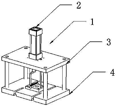
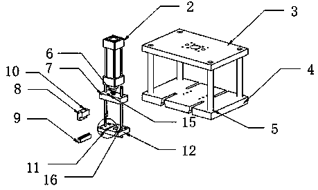
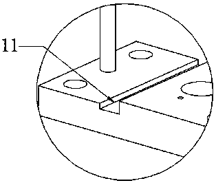
[0021] Such as Figure 1 to Figure 5 As shown, the fixture device 1 for steel cutting includes a power cylinder 2, the bottom end of the power cylinder 2 is provided with a cylinder telescopic rod 6, the bottom of the power cylinder 2 is provided with a support plate 3, and the edge of the support plate 3 is provided with several A support column 5, a base 4 is provided below the support column 5, a slide block 7 is installed below the telescopic rod 6 of the cylinder, two slide block holes 15 are provided inside the slide block 7, and the edges of both sides of the slide block 7 are provided with There is a slide bar 16, a first fixture 8 is pro...


PUM


Abstract

The invention discloses a clamp device for steel plate cutting. The device comprises a power cylinder, a cylinder telescopic rod is arranged at the bottom of the power cylinder, a support plate is arranged on the lower portion of the power cylinder, multiple support columns are arranged on the edge of the support plate, a base is arranged on the lower portion of the support column, a sliding blockis installed on the lower portion of the cylinder telescopic rod, and internally provided with two sliding block holes, sliding rods are arranged on the edges of the two sides of the sliding block, afirst clamp is arranged on the lower portion of the sliding block, a second clamp base is arranged at the bottoms of the sliding rods, and the second clamp is internally provided with a second clampgroove. A user directly installs the second clamp on the second clamp base through a fixed groove, a steel plate is placed on the second fixture through the second clamp groove, the cylinder telescopic rod is driven by the power cylinder to stretch, and then the sliding block is pressed, so that the steel plate is clamped by the fire clamp and the second clamp, and then cutting is conducted.

Description

technical field [0001] The invention relates to a clamp device, more precisely, a clamp device for cutting steel plates. Background technique [0002] Most of the construction industry needs to use large steel plates. In the production of steel plates, the steel plates produced are all of the same length. If you need steel plates with different lengths, you need to use a cutting machine. Most of the large steel plates are heavy, and manpower is very laborious. In order to lift it up, not to mention cutting it into steel plates with different lengths and lengths, and during the cutting process, due to the action of the cutting machine, the steel pipe vibrates, and it is difficult to control the manpower. The existing cutting method can only face the steel plate on the ground Cutting, this method is easy to shake the steel plate, increases the difficulty of cutting, and causes a waste of human resources in the processing process. Contents of the invention [0003] The p...

Claims


Application Information

Patent Timeline
Patent Type & Authority Applications(China)
IPC IPC(8): B23Q3/00
CPCB23Q3/00B23Q2703/04
Inventor 丁茂明
Owner 丁茂明
Learn More