
Pulse-controlled silicon controlled rectifier floating charger

A pulse control, thyristor technology, applied in the field of electronics, can solve problems such as affecting battery capacity and life, battery environment pollution, waste, etc.

Inactive Publication Date: 2018-05-29
CHONGQING NINGLAI SCI & TRADE
View PDF0 Cites 0 Cited by
  • Summary
  • Abstract
  • Description
  • Claims
  • Application Information

AI Technical Summary

Problems solved by technology

[0002] With the enrichment of modern life, there are more and more types of electrical appliances using batteries, such as security equipment, digital machines, mobile phones, etc. For this reason, there are also many types of chargers, but there is a lack of a low-carbon battery in these types. Various types of environmentally friendly charging circuits
The first significance is that the charging supervisor in the current product is the circuit transistor that stops charging and is easily damaged. Once damaged, the charger becomes garbage.
It is understood that this failure has become the main failure point, and it is a great waste to turn it into garbage just because of this damage. People are often lost)
The second significance is that during the charging process, the battery is not charged scientifically, so it affects the capacity and life of the battery. It is also easy to turn the battery into garbage prematurely, which forms waste and pollutes the environment
(Waste batteries pollute the environment)
The reason for not achieving the most scientific charging is that the current products either only use DC to charge the battery, but do not use a better method, such as constant current charging; or even though they can be charged with a constant current source , but there are still some conveniences in use, or it is not scientific enough on the line, etc., so it should be enriched and developed

Method used

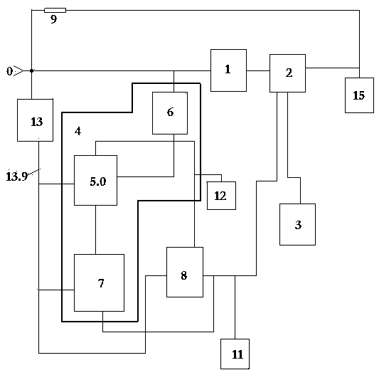
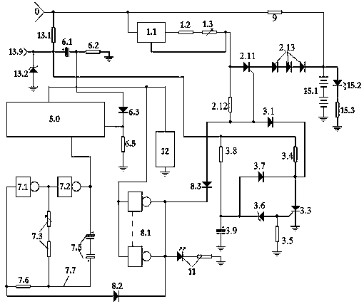
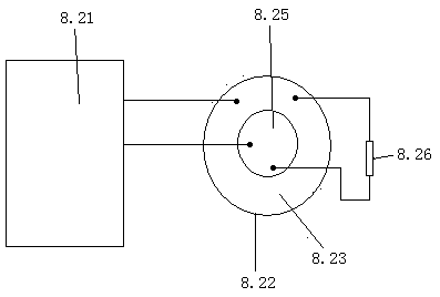

Image

  • Pulse-controlled silicon controlled rectifier floating charger
  • Pulse-controlled silicon controlled rectifier floating charger
  • Pulse-controlled silicon controlled rectifier floating charger

Examples


Embodiment Construction

[0095] figure 1 , 2 , 3, 4, 5 examples have gone out a kind of implementation making example.

[0096] 1. Selection of components: The pulse capacitor adopts a non-polar capacitor.

[0097] The excitation parallel gate and the gate 1 circuit and the gate 2 circuit are welded by an inverter inside an integrated circuit CD4069, and the excitation parallel gate is connected in parallel with four inverters.

[0098] The charging display unit is composed of a charging display luminous tube connected in series with a charging display protection resistor.

[0099] The current limit indicator is an LED.

[0100] 2. Plate making and welding: press figure 2 To make the circuit control board, press figure 2 Schematic of soldered components. Pronunciation as image 3 Welded as shown.

[0101] 3. Power-on inspection and debugging.

[0102] 1. Check the constant current source part.

[0103] Connect a triode to form an adjustable voltage regulator analog circuit instead of the ch...


PUM


Abstract

A pulse-controlled silicon controlled rectifier (SCR) floating charger belongs to the technical field of electronics. The pulse-controlled SCR floating charger is composed of a trickle resistor, a constant current unit, an SCR charging unit, an SCR pulse unit, a voltage stabilizing unit of an integrated circuit, a counting unit, an end unit, a charging display unit, an end sound unit and a load unit. A three-terminal voltage regulator is connected in a constant-current mode, and thus, a constant current can be provided for the SCR charging unit. The SCR charging unit is controlled by the SCR pulse unit. Therefore, a pulse type constant-current charging process is formed. When the timing in the counting unit ends, the end sound unit sends out a sound prompt, the end unit is started, the SCRcharging unit is clamped to stop charging, the charging display unit stops display, the oscillation in the counting unit stops until the artificial end, and the trickle resistor provides a maintaining trickle current for a charged battery. The units are connected scientically. Comprehensive utilization is achieved. The pulse-controlled SCR floating charger is easy to produce and debug, and is very suitable for micro enterprises.

Description

technical field [0001] It belongs to the field of electronic technology. Background technique [0002] With the enrichment of modern life, there are more and more types of electrical appliances using batteries, such as security equipment, digital machines, mobile phones, etc. For this reason, there are also many types of chargers, but there is a lack of a low-carbon battery in these types. Various types of environmentally friendly charging circuits. The first significance is that in current products, the charging director, which is the circuit transistor that stops charging, is easily damaged. Once damaged, the charger becomes garbage. It is understood that this failure has become the main failure point, and it is a great waste to turn it into garbage just because of this damage. People are often lost). The second significance is that during the charging process, the battery is not charged scientifically, so it affects the capacity and life of the battery. It is also eas...

Claims


Application Information

Patent Timeline
Patent Type & Authority Applications(China)
IPC IPC(8): H02J7/00
CPCH02J7/007H02J7/0047
Inventor 不公告发明人
Owner CHONGQING NINGLAI SCI & TRADE
Learn More