Fixing structure of plastic mould

A fixed structure and plastic mold technology, applied in the direction of manufacturing tools, workpiece clamping devices, etc., can solve the problems of the use of fixed structures, reduce the accuracy of processing, and the fixed structure cannot be processed by mold size adjustment, etc., to achieve good fixing effect, Efficient and fast effect

Inactive Publication Date: 2019-01-25
HUANGSHI DINGSHENG MOLD CO LTD
View PDF0 Cites 0 Cited by
  • Summary
  • Abstract
  • Description
  • Claims
  • Application Information

AI Technical Summary

Problems solved by technology

[0003] In the process of plastic mold processing, in order to prevent the mold from sliding and reduce the precision of processing, it is necessary to use a mold fixing structure to fix the mold to improve the stability of plastic mold processing. Therefore, the use of mold fixing structures is more common; existing The fixed structure has certain disadvantages in use. In order to meet different use requirements, the size of the plastic mold is different, and the fixed structure cannot be adjusted according to the size of the processing mold. The scope of use is limited, which causes the use of the fixed structure. To a certain extent, for this reason, we propose a fixed structure for plastic molds

Method used


Image

  • Fixing structure of plastic mould
  • Fixing structure of plastic mould

Examples


Embodiment Construction

[0014] The technical solutions in the embodiments of the present invention will be clearly and completely described below in conjunction with the accompanying drawings in the embodiments of the present invention. Obviously, the described embodiments are only part of the embodiments of the present invention, not all of them.

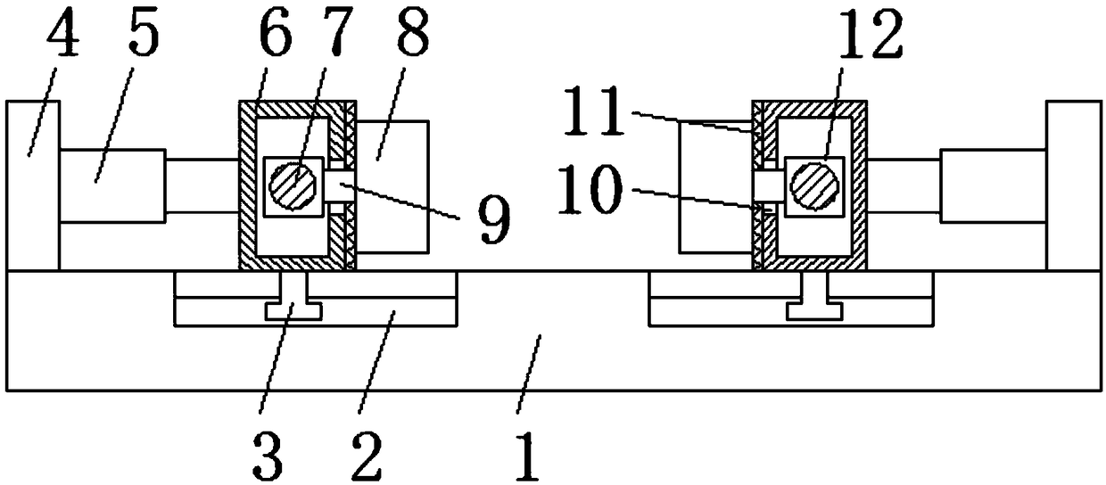
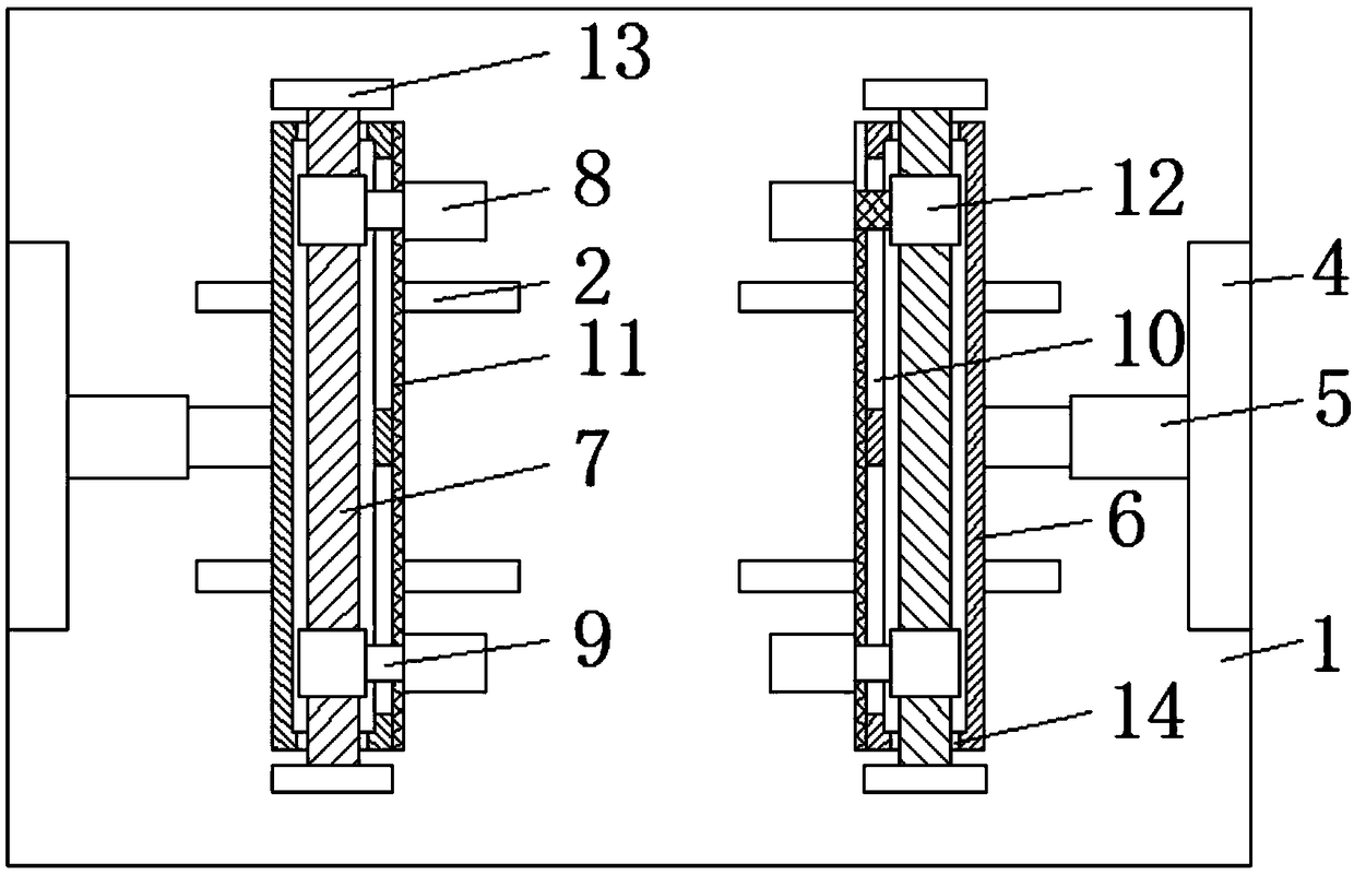
[0015] refer to Figure 1-2 , a fixed structure of a plastic mold, including a base 1, a support plate 4 is fixed at the center of both sides of the upper end of the base 1, a hydraulic telescopic rod 5 is installed at the center of the corresponding side of the two support plates 4, and two hydraulic telescopic The output shaft of the rod 5 is connected with an extrusion box 6, and the two extrusion boxes 6 are limited by a sliding mechanism. When the plastic mold is fixed, the plastic mold is first placed on the base 1 between the two extrusion boxes 6 On the top, the hydraulic telescopic rod 5 is connected to the external power supply through a wire, a...


PUM


Abstract

The invention relates to the technical field of plastic moulds, in particular to a fixing structure of a plastic mould. The centers of the two sides of the upper end of a base are fixedly provided with supporting plates respectively, the centers of the corresponding sides of the two supporting plates are provided with hydraulic telescopic rods respectively, output shafts of the two hydraulic telescopic rods are connected with extrusion boxes respectively, the two extrusion boxes conduct limiting through sliding mechanisms, bearings penetrate through the two sides of the two extrusion boxes respectively, the inner sides of the two extrusion boxes are provided with screw rods respectively, the two ends of the screw rods penetrate through the bearings and extend to the outer sides of the extrusion boxes, the two ends of the two screw rods are provided with rotary knob respectively, the outer sides of the two ends of the two screw rods are provided with sliding blocks respectively, the corresponding sides of the sliding blocks are connected with connecting blocks respectively, the two ends of the corresponding sides of the two extrusion boxes are provided with sliding grooves respectively, the connecting blocks penetrate through the sliding grooves and extend to the outer sides of the extrusion boxes, and the other ends of the connecting blocks are fixedly provided with limiting plates respectively. The fixing structure of the plastic mould has the advantages that the structure is simple, the plastic moulds with different sizes can be fixed rapidly, the fixing effect is good, and the efficiency is quick.

Description

technical field [0001] The invention relates to the technical field of plastic molds, in particular to a fixing structure for plastic molds. Background technique [0002] Plastic mold, an abbreviation for a combined plastic mold for compression molding, extrusion molding, injection, blow molding and low foam molding. [0003] In the process of plastic mold processing, in order to prevent the mold from sliding and reduce the precision of processing, it is necessary to use a mold fixing structure to fix the mold to improve the stability of plastic mold processing. Therefore, the use of mold fixing structures is more common; existing The fixed structure has certain disadvantages in use. In order to meet different use requirements, the size of the plastic mold is different, and the fixed structure cannot be adjusted according to the size of the processing mold. The scope of use is limited, which causes the use of the fixed structure. To a certain extent, for this reason, we pro...

Claims


Application Information

Patent Timeline
IPC IPC(8): B25B11/00
CPCB25B11/00
Inventor 陈胜王建曹礼连林华兵李涛
Owner HUANGSHI DINGSHENG MOLD CO LTD
Why Eureka
Try Eureka