Assembly line grabbing mechanical arm

A mechanical arm and assembly line technology, applied in the directions of manipulators, manufacturing tools, chucks, etc., can solve the problems of falling ceramic workpieces with clamping force, unfavorable glaze sealing operation, and difficulty in grasping clamping force, and achieve the effect of speeding up the curing process.

Active Publication Date: 2022-05-10
徐州常青生物科技有限公司
View PDF11 Cites 0 Cited by
  • Summary
  • Abstract
  • Description
  • Claims
  • Application Information

AI Technical Summary

Problems solved by technology

[0002] In the production process of ceramic products, in order to make the appearance more beautiful, the surface often needs to be glazed. When some ornamental ceramic products are glazed, the inner and outer surfaces can be glazed at the same time. However, for some For ceramic products of food or wine, it is often necessary to process the inner and outer surfaces step by step when sealing the glaze; in the prior art, the mechanical arm is usually used to clamp the outer part of the ceramic workpiece, and then the ceramic workpiece is slowly transferred The sealing process can be carried out in the sealing glaze tank. Although this can improve the processing efficiency to a certain extent, the clamping force of this traditional clamping method is difficult to grasp. If the clamping force is too large, the ceramic workpiece may be damaged. If the holding force is too small, it may cause the ceramic workpiece to fall, and the glaze liquid will often enter the interior of the ceramic workpiece during the glaze sealing process. In addition, clamping on the outside of the ceramic workpiece will also affect the The outer surface of the workpiece is covered, which is not conducive to the glaze sealing operation

Method used


Image

  • Assembly line grabbing mechanical arm
  • Assembly line grabbing mechanical arm
  • Assembly line grabbing mechanical arm

Examples


Embodiment 1

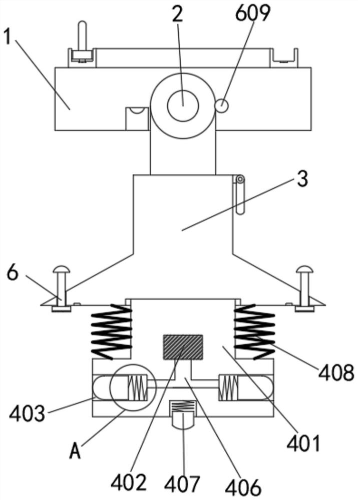
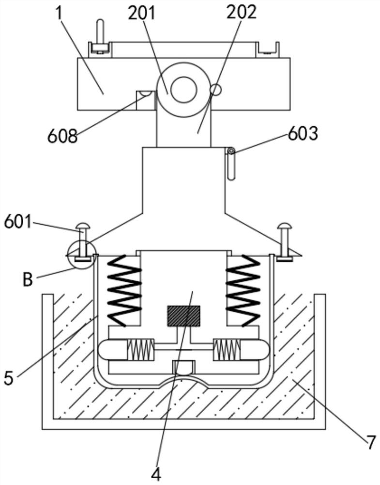
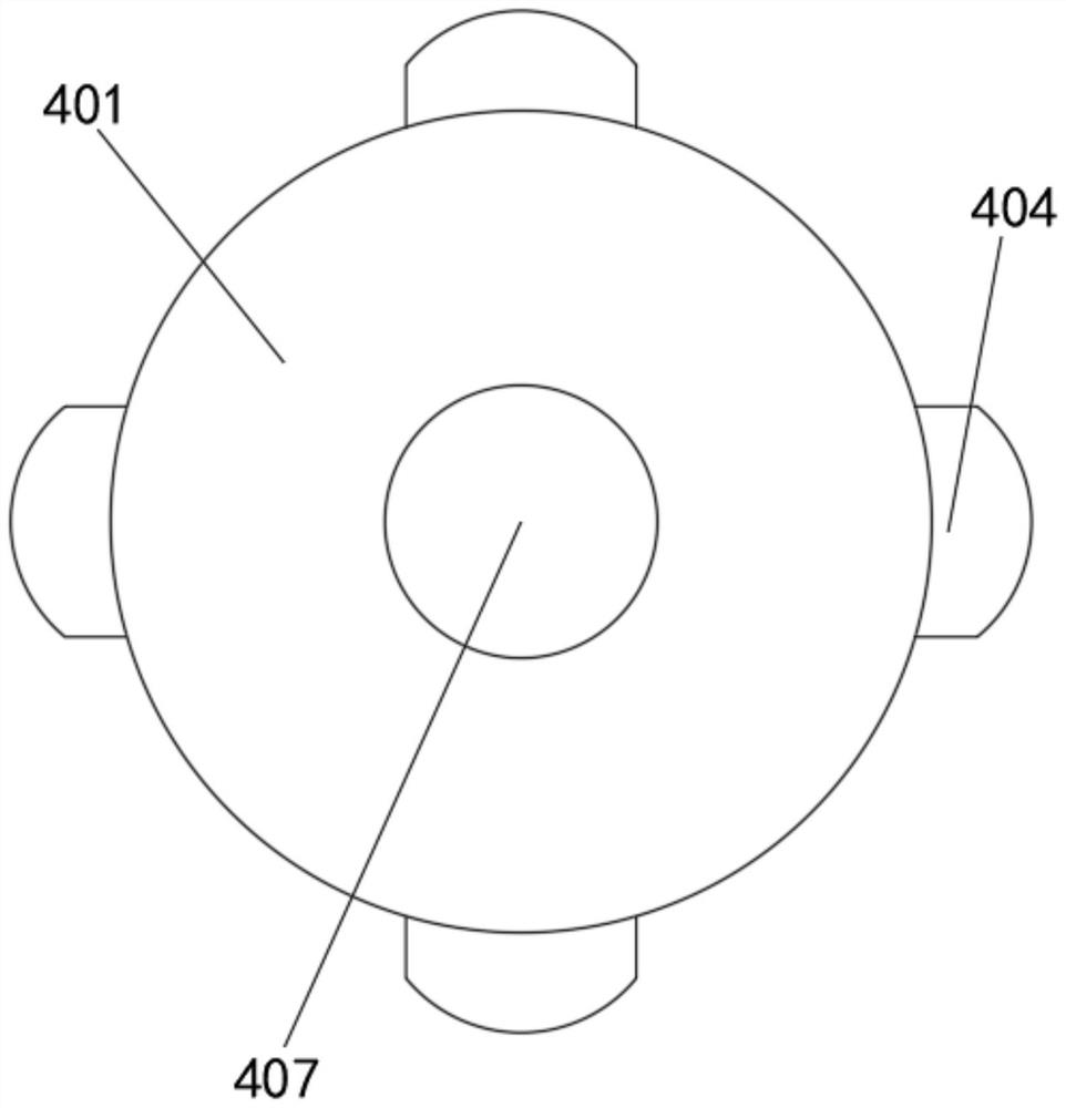
[0032] see figure 1 - Figure 4, an assembly line grabbing mechanical arm, including a fixed block 1, a rotating assembly 2 is movably installed in the middle of the fixed block 1, and a mounting platform 3 is movably socketed on the lower end of the rotating assembly 2, and an internal clamping device is movably installed at the lower end of the mounting platform 3 Mechanism 4, a ceramic workpiece 5 is detachably installed on the outside of the internal clamping mechanism 4, a curing auxiliary mechanism 6 is movably installed on the upper end of the fixed block 1, a sealing glaze pool 7 is arranged on the outside of the ceramic workpiece 5, and the rotating assembly 2 includes a rotating round block 201 , the lower end of the rotating round block 201 is fixedly installed with an installation column 202, the rotating round block 201 is movably installed in the middle of the fixed block 1, and the upper end of the installation column 202 is fixedly connected with the rotating r...

Embodiment 2

[0040] see Figure 5 - Figure 8 , an assembly line grabbing mechanical arm, including a fixed block 1, a rotating assembly 2 is movably installed in the middle of the fixed block 1, and a mounting platform 3 is movably socketed on the lower end of the rotating assembly 2, and an internal clamping device is movably installed at the lower end of the mounting platform 3 Mechanism 4, the ceramic workpiece 5 is detachably installed on the outside of the internal clamping mechanism 4, the upper end of the fixed block 1 is movably installed with a curing auxiliary mechanism 6, the rotating assembly 2 includes a rotating round block 201, and the lower end of the rotating round block 201 is fixedly installed with an installation The column 202 and the rotating round block 201 are movably installed in the middle of the fixed block 1, and the upper end of the installing column 202 is fixedly connected with the rotating round block 201, so that when the rotating round block 201 rotates, ...


PUM


Abstract

The invention relates to the technical field of mechanical arm manufacturing, and discloses an assembly line grabbing mechanical arm which comprises a fixing block, a rotating assembly is movably installed in the middle of the fixing block, the lower end of the rotating assembly is movably sleeved with a mounting table, and an internal clamping mechanism is movably installed at the lower end of the mounting table. A ceramic workpiece is detachably installed outside the internal clamping mechanism, a curing auxiliary mechanism is movably installed at the upper end of the fixing block, the internal clamping mechanism comprises a movable seat, a limiting sliding groove is horizontally formed in the lower end of the movable seat, the curing auxiliary mechanism comprises a fine adjustment straight rod, and a sensing assembly is fixedly installed at the lower end of the fine adjustment straight rod. Through mutual cooperation between a pressing switch and an abutting sliding block, after the pressing switch is switched on, air supply equipment can supply air to the interior of a limiting sliding groove, and then the abutting sliding block can extend out of the limiting sliding groove under pushing of air pressure and abut against the inner wall of a ceramic workpiece; therefore, the effect that the ceramic workpiece can be automatically and rapidly fixed and limited is achieved.

Description

technical field [0001] The invention relates to the technical field of manipulator manufacturing, in particular to an assembly line grabbing manipulator. Background technique [0002] In the production process of ceramic products, in order to make the appearance more beautiful, the surface often needs to be glazed. When some ornamental ceramic products are glazed, the inner and outer surfaces can be glazed at the same time. However, for some For food or wine ceramic products, it is often necessary to process the inner and outer surfaces step by step when sealing the glaze; in the prior art, the mechanical arm is usually used to clamp the outer part of the ceramic workpiece, and then the ceramic workpiece is slowly transferred Carry out the glaze treatment in the glaze pool, although this can improve the processing efficiency to a certain extent, but the clamping force of this traditional clamping method is difficult to master, and the clamping force is too large, which may c...

Claims


Application Information

Patent Timeline
Patent Type & Authority Applications(China)
IPC IPC(8): B25J15/00
CPCB25J15/0047
Inventor 朱守富
Owner 徐州常青生物科技有限公司
Why Eureka
Try Eureka