
A low-floor rail vehicle roof and a low-floor rail vehicle

A rail vehicle and low-floor technology, applied in the field of rail transit, can solve problems such as difficult maintenance, limited installation space, and bulky roof structure, and achieve the effect of light weight and convenience

Active Publication Date: 2019-01-25
ZHUZHOU ELECTRIC LOCOMOTIVE CO
View PDF10 Cites 0 Cited by
  • Summary
  • Abstract
  • Description
  • Claims
  • Application Information

AI Technical Summary

Problems solved by technology

[0003] Due to the small distance between the chassis of low-floor rail vehicles and the rail surface, the installation space provided by the bottom of low-floor rail vehicles is extremely limited. The equipment is usually mounted on the roof of the low-floor rail vehicle, resulting in many drawbacks of existing low-floor rail vehicles
For example, the existing low-floor rail car roof usually includes a left beam, a right beam and a roof plate welded between the left beam and the right beam, and the external equipment is usually installed on the roof plate, in order to make the roof plate have Sufficient strength to support external equipment, the roof plate is usually made of thicker steel plates, resulting in a bulky structure for the roof of low-floor rail vehicles
Another example, the left side wall and the right side wall of the existing low-floor rail vehicle are usually welded to the bottom of the roof of the low-floor rail vehicle, which is inconvenient to disassemble and assemble the roof of the low-floor rail vehicle, and the maintenance is relatively difficult
Therefore, the structure of the existing low-floor rail vehicle roof is relatively heavy and difficult to maintain, which is not conducive to the realization of light weight and convenience

Method used


Image

  • A low-floor rail vehicle roof and a low-floor rail vehicle
  • A low-floor rail vehicle roof and a low-floor rail vehicle
  • A low-floor rail vehicle roof and a low-floor rail vehicle

Examples


Embodiment Construction

[0041] The following will clearly and completely describe the technical solutions in the embodiments of the present invention with reference to the accompanying drawings in the embodiments of the present invention. Obviously, the described embodiments are only some, not all, embodiments of the present invention. Based on the embodiments of the present invention, all other embodiments obtained by persons of ordinary skill in the art without making creative efforts belong to the protection scope of the present invention.

[0042] In order to enable those skilled in the art to better understand the solution of the present invention, the present invention will be further described in detail below in conjunction with the accompanying drawings and specific embodiments.

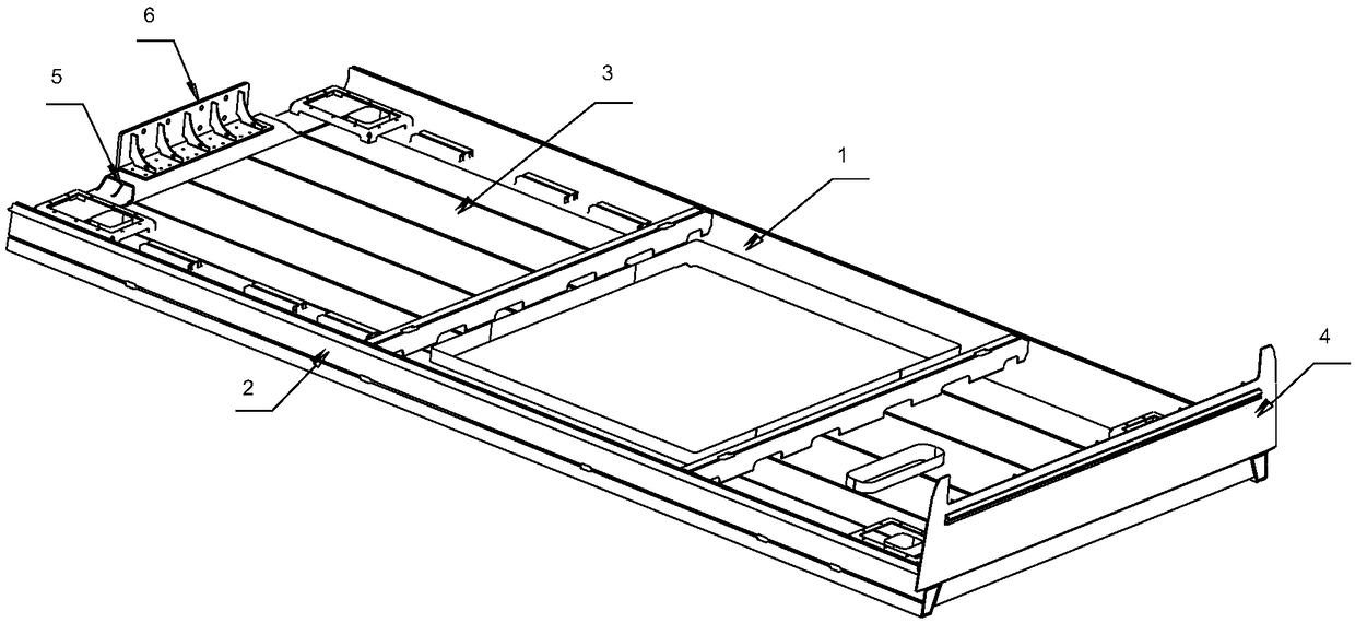
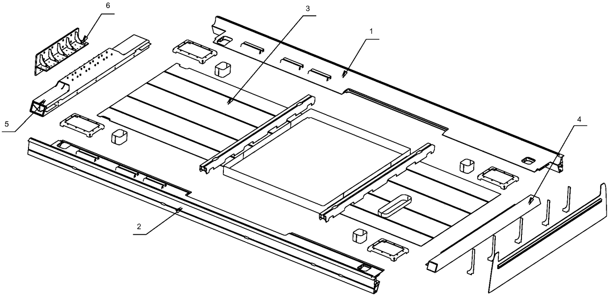
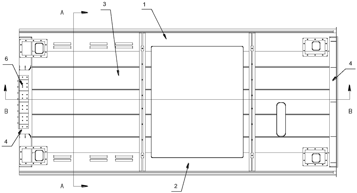
[0043] Please refer to Figure 1 to Figure 8 , figure 1 A structural schematic diagram of a roof of a low-floor rail vehicle provided for a specific embodiment of the present invention; figure 2 for figure 1 Exp...


PUM


Abstract

The invention discloses alow-floor rail vehicle top covercomprising aleft side beam, aright side beam and atop cover plate fixed between the left side beam and the right side beam, a left side beam and a right side beam are respectively provide with a left support groove and a right support groove and are respectively provided with a left bite groove and a right bite groove for detachable connection corresponding to that left side wall and the right side wall, and the left side beam and the right side beam are also respectively provided with a left reinforcement part and a right reinforcementpart for enhance the bending strength of the cross section. The left and right stiffeners are advantageous to improve the bending strength of the left and right beams, which makes it possible for theleft and right beams to bear heavy loads. The left support groove, the right support groove and the top cover plate can be used to support the external equipment so as to reduce the load on the top cover plate. The left side beam is detachably connected to the left side wall and the right side beam is detachably connected to the right side wall, which provides the possibility for convenient disassembly, thereby facilitating lightweight and convenience. The invention also discloses a low-floor rail vehicle comprising a roof of the low-floor rail vehicle.

Description

technical field [0001] The invention relates to the field of rail transportation, in particular to a top cover of a low-floor rail vehicle. The invention also relates to a low-floor rail vehicle. Background technique [0002] The underframe of low-floor rail vehicles usually has a small vertical distance from the rail surface, and there is no need to set up a separate platform. It has many advantages such as easy route planning, low investment cost, and short construction period, and has a broad market prospect. [0003] Due to the small distance between the chassis of low-floor rail vehicles and the rail surface, the installation space provided by the bottom of low-floor rail vehicles is extremely limited. The equipment is usually mounted on the roof of the low-floor rail vehicle, leading to a number of disadvantages of existing low-floor rail vehicles. For example, the existing low-floor rail car roof usually includes a left beam, a right beam and a roof plate welded bet...

Claims


Application Information

Patent Timeline
IPC IPC(8): B61D17/12
CPCB61D17/12
Inventor 王丽陈赞平刘永强王国军李丽苑明
Owner ZHUZHOU ELECTRIC LOCOMOTIVE CO
Learn More