
Method for ceramic bonding by utilizing ceramic ware bonding device

A control device and bonding technology, applied in the direction of connecting components, material gluing, mechanical equipment, etc., can solve the problems of low quality, waste of materials, low efficiency, etc., and achieve the effect of convenient operation, improved work quality and efficiency, and simple structure

Inactive Publication Date: 2019-01-25
缙云新间新材料有限公司
View PDF0 Cites 7 Cited by
  • Summary
  • Abstract
  • Description
  • Claims
  • Application Information

AI Technical Summary

Problems solved by technology

[0002] Ceramics can be made into bowls or handicrafts in daily life, but they are used in industry or other fields due to their excellent characteristics, but ceramic products need to be bonded with other materials for use, while the existing ceramic glue The bonding strength is sufficient to meet some strength requirements, but the bonding must ensure accurate alignment in order to ensure that there is no deviation in the bonding, and manual alignment will produce displacement deviations to some extent, resulting in low quality and low efficiency. Therefore, there is an urgent need for a method for ceramic bonding using a ceramic firing product bonding device. When the device is used for ceramic bonding, it can automatically perform positioning and clamping, and then perform bonding to prevent bonding failure caused by position deviation. Thereby reducing material waste and improving work quality and efficiency

Method used


Image

  • Method for ceramic bonding by utilizing ceramic ware bonding device
  • Method for ceramic bonding by utilizing ceramic ware bonding device
  • Method for ceramic bonding by utilizing ceramic ware bonding device

Examples


Embodiment Construction

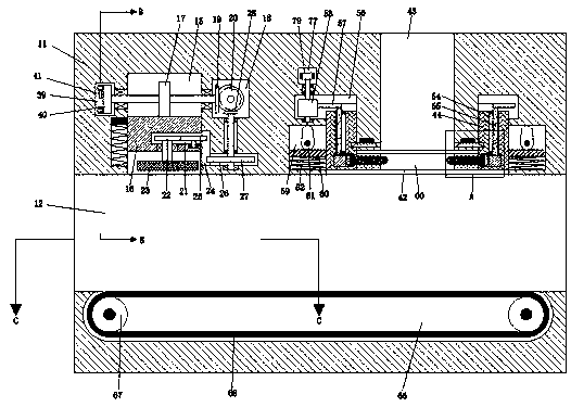
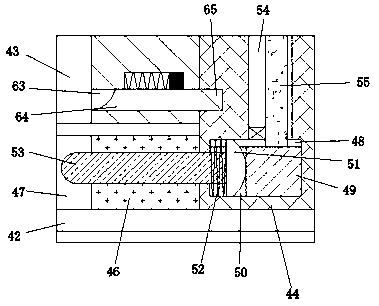
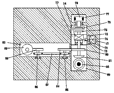
[0019] Combine below Figure 1-7 The present invention is described in detail, and for convenience of description, the orientations mentioned below are now stipulated as follows: figure 1 The up, down, left, right, front and back directions of the projection relationship itself are the same.

[0020] refer to Figure 1-7 , according to an embodiment of the present invention, a method for ceramic bonding using a ceramic fired product bonding device includes a body 11, a bonding cavity 12 is arranged in the body 11, and a bonding cavity 12 is set in the upper left of the bonding cavity 12. There is a smearing device. The smearing device first clamps the front and rear sides of the ceramic, and then smears the bonding glue on the upper end of the ceramic. A bonding device is arranged on the upper right of the bonding cavity 12. Through the bonding device, the required The material bonded to the upper end of the ceramic is clamped, and then pressed on the glue for bonding. The l...


PUM


Abstract

The invention discloses a method for ceramic bonding by utilizing a ceramic ware bonding device. The bonding device comprises a device body, a bonding cavity is formed in the device body, and a smearing device is arranged on the upper left portion in the bonding cavity; firstly, the smearing device clamps the front and back sides of ceramic, glue is smeared on and bonded to the upper end of the ceramic, and the bonding device is arranged on the upper right portion in the bonding cavity; materials needing to be bonded to the upper end of the ceramic are clamped through the bonding device and pressed to the glue for bonding, a conveying device is arranged on the lower side in the bonding cavity, and fixed point conveying is achieved through the conveying device; when the bonding device is utilized for ceramic bonfing, locating and clamping can be automatically conducted for bonding again, it is avoided that in the bonding process, due to position deflection, bonding fails, and materialsare wasted, and the work quality and efficiency are improved.

Description

technical field [0001] The invention relates to the technical field of ceramic processing, in particular to a ceramic bonding method using a ceramic fired product bonding device. Background technique [0002] Ceramics can be made into bowls or handicrafts in daily life, but they are used in industry or other fields due to their excellent characteristics, but ceramic products need to be bonded with other materials for use, while the existing ceramic glue The bonding strength is sufficient to meet some strength requirements, but the bonding must ensure accurate alignment in order to ensure that there is no deviation in the bonding, and manual alignment will produce displacement deviations to some extent, resulting in low quality and low efficiency. Therefore, there is an urgent need for a method for ceramic bonding using a ceramic firing product bonding device. When the device is used for ceramic bonding, it can automatically perform positioning and clamping, and then perform ...

Claims


Application Information

Patent Timeline
Patent Type & Authority Applications(China)
IPC IPC(8): F16B11/00C04B37/00
CPCF16B11/006C04B37/00
Inventor 李志成
Owner 缙云新间新材料有限公司
Learn More