imaging lens

An imaging lens and lens technology, applied in the field of imaging lens, can solve problems such as manufacturing difficulties and deterioration of peripheral imaging quality, and achieve the effects of correcting distortion, reducing loss of imaging effect, and optimizing optical path adjustment ability

Active Publication Date: 2021-11-09
FUJIN PRECISION IND JINCHENG CO LTD
View PDF7 Cites 0 Cited by
  • Summary
  • Abstract
  • Description
  • Claims
  • Application Information

AI Technical Summary

Problems solved by technology

However, the design of imaging lenses with low length and large aperture often faces more aberrations, resulting in deterioration of peripheral imaging quality and manufacturing difficulties

Method used


Image

  • imaging lens
  • imaging lens
  • imaging lens

Examples


no. 1 example

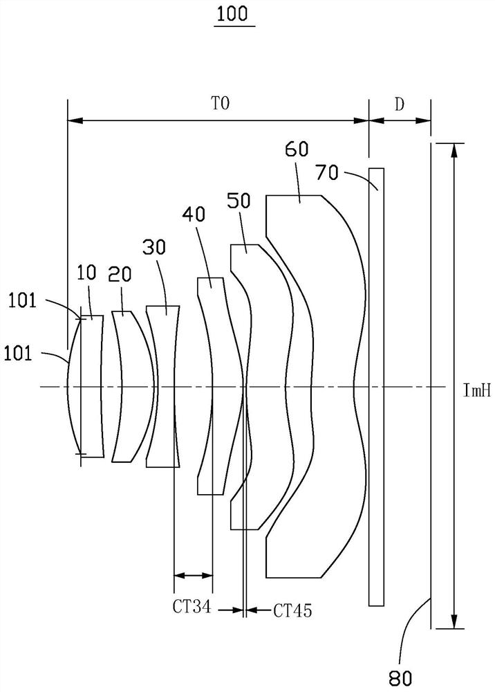
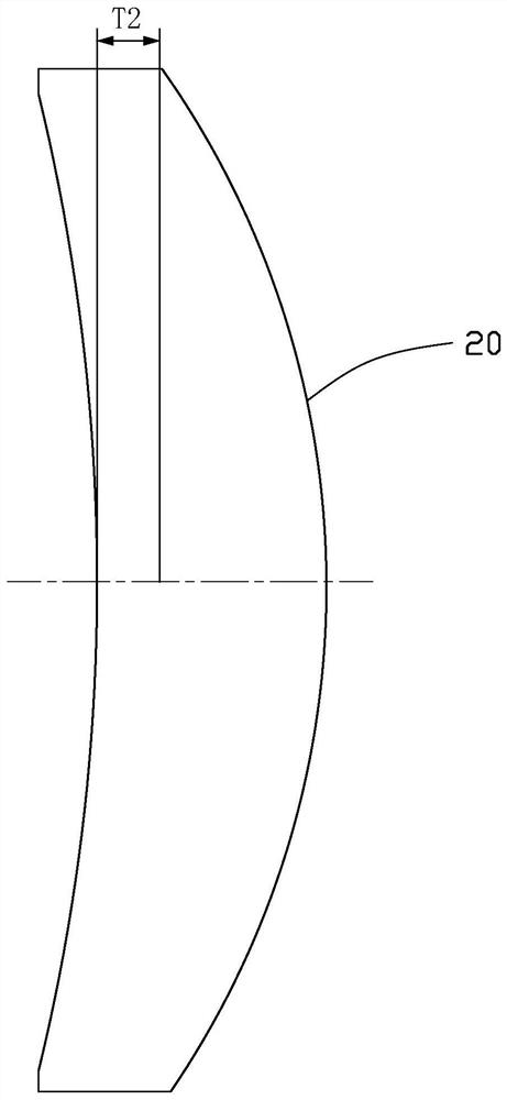
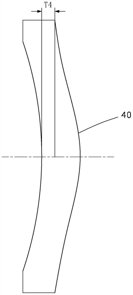
[0060] see figure 1 , figure 1 It is the imaging lens 100 provided in the first embodiment of the present invention. The imaging lens 100 includes a lens element, a filter 70 and an image sensor 80 which are sequentially arranged along the optical axis. The lens element 10, the second lens element 20 with positive refractive power, the third lens element 30 with negative refractive power, the fourth lens element 40 with positive refractive power, the fifth lens element 50 with negative refractive power, The sixth lens element 60 with negative power is formed.

[0061] The lens element with positive refractive power converges the light beam; the lens element with negative refractive power diverges the light beam, and is mainly used to receive incident light from a wide range of angles and correct part of the spherical aberration.

[0062] The imaging lens 100 further includes an aperture (ApertureStop) 101 disposed on the object side of the first lens element 10 .

[0063] Th...

no. 2 example

[0112] see Figure 7 The imaging lens 200 provided by the second embodiment is basically the same in structure as the imaging lens 100 provided by the first embodiment, the difference is that the radius of curvature, thickness, refractive index and Abbe number of the imaging lens 100 are the same as those of the first embodiment. Examples vary. By substituting the data in Table 4 and Table 5 into the above expression (a), the aspheric shape of each lens surface in the imaging lens 200 according to the second embodiment of the present invention can be known.

[0113] Table 4

[0114]

[0115]

[0116] table 5

[0117] Aspheric coefficient S1 S2 S3 S4 S5 S6 A4 -1.70E-3 -0.0301 -0.0308 -0.0197 -0.1563 -0.1491 A6 -0.0286 -3.64E-3 -0.0180 -0.0578 8.18E-4 0.0413 A8 0.0259 -0.0363 -0.0181 0.0348 0.0157 -0.0264 A10 -0.0279 0.0122 8.27E-3 -0.0133 0.0146 0.0146 Aspheric coefficient S7 S8 S9 S10 S11 S12 A4 0....


PUM


Abstract

The present invention provides an imaging lens, comprising a lens element and an image sensor. The lens element consists of a first lens element, a second lens element, a third lens element, a fourth lens element, a Composed of five lens elements and a sixth lens element; the first lens element includes a first surface facing the object plane side and a second surface facing the image plane side; the second lens element includes a third surface facing the object plane side and the fourth surface towards the image plane side; the third lens element includes a fifth surface towards the object plane side and a sixth surface towards the image plane side; the fourth lens element has a seventh surface towards the object plane side surface and the eighth surface towards the image plane side; the fifth lens element includes a ninth surface towards the object plane side and a tenth surface towards the image plane side; the imaging lens satisfies the following conditional formula: 8.3

Description

technical field [0001] The invention relates to imaging technology, in particular to an imaging lens. Background technique [0002] In recent years, with the rise of portable electronic products with photography functions, the demand for imaging lenses has increased day by day. The photosensitive element of a general imaging lens is nothing more than a photosensitive coupling element (ChargeCoupledDevice; CCD) or a complementary metal oxide semiconductor element (ComplementaryMetal-Ox i deSemi conduTPorSensor; CMOSSensor), and with the progress of semiconductor manufacturing technology, The pixel size of the photosensitive element is reduced, and the imaging lens is gradually developed in the direction of high pixel, so the requirements for imaging quality are also increasing. [0003] Traditional imaging lenses mounted on portable devices mostly use three-element or four-element lens structures. However, due to the continuous development of portable devices in the directio...

Claims


Application Information

Patent Timeline
Patent Type & Authority Patents(China)
IPC IPC(8): G02B13/00G02B13/18
CPCG02B13/0045G02B13/18G02B9/62G02B27/0025
Inventor 杨琬茜
Owner FUJIN PRECISION IND JINCHENG CO LTD
Why Eureka
Try Eureka