
Impulse Loading Apparatus for Non-Static Inclined Conveyor Chains

A loading device and non-static technology, which is applied in the direction of measuring devices, machine/structural component testing, instruments, etc., can solve the problems that cannot accurately reflect the real load-carrying performance of the conveyor chain, and achieve high self-adaptive performance and fast adjustment Effect

Active Publication Date: 2020-04-03
四川省农业机械科学研究院
View PDF9 Cites 0 Cited by
  • Summary
  • Abstract
  • Description
  • Claims
  • Application Information

AI Technical Summary

Problems solved by technology

Therefore, this load loading method cannot accurately reflect the real load-carrying performance of the conveyor chain during operation.

Method used


Image

  • Impulse Loading Apparatus for Non-Static Inclined Conveyor Chains
  • Impulse Loading Apparatus for Non-Static Inclined Conveyor Chains
  • Impulse Loading Apparatus for Non-Static Inclined Conveyor Chains

Examples


Embodiment Construction

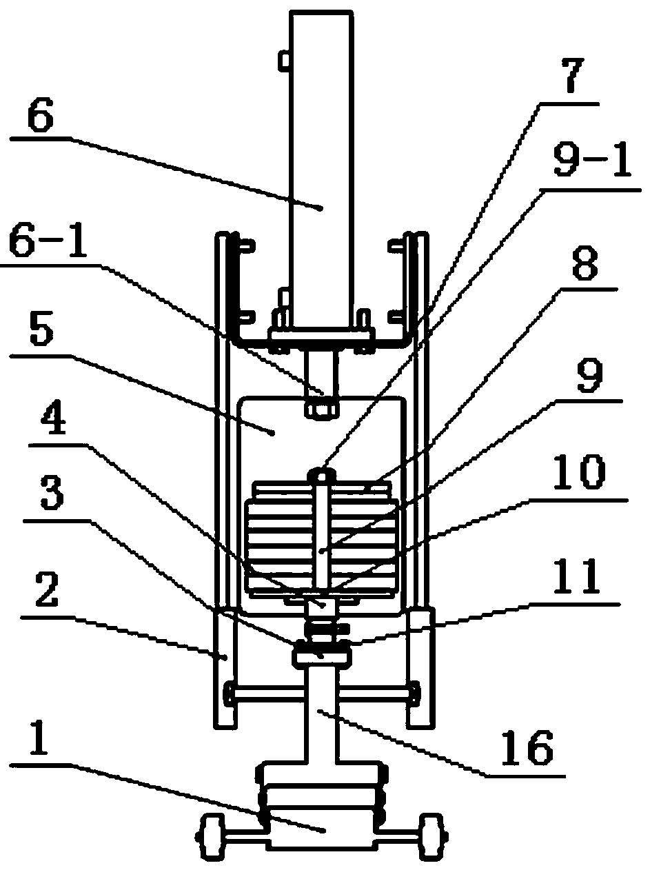
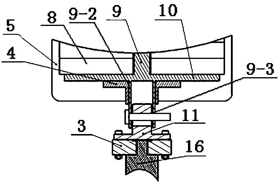
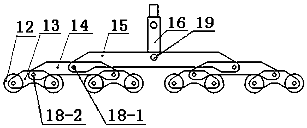
[0015] see Figure 1 ~ Figure 4 , this embodiment is suitable for the pulse load loading device of non-static inclined conveyor chain, including loading trolley 1, guide rail 2, MIK-LCLY force sensor 3, counterweight frame base 4, counterweight frame 5, telescopic hydraulic cylinder 6, frame 7. Counterweight 8, counterweight rod 9, counterweight base 10, flange shaft 11. Loading trolley 1 comprises loading wheel 12, wheel axle frame 13, wheel train bridge frame 14, wheel train girder 15, articulated rod 16, guide rod 17, guide bearing 18, articulated rod connecting shaft 19, guide rod 20.

[0016] see figure 1 , figure 2 , telescopic hydraulic cylinder 6 cylinder body is fixed on the bottom of frame 7 with bolts, and its telescopic rod 6-1 passes through the bottom center hole of frame 7 and the top center hole of counterweight frame 5 and uses nuts to connect the telescopic hydraulic cylinder The telescopic link of 6 is fixedly connected with counterweight frame 5. The c...


PUM


Abstract

The invention is a pulse load loading device suitable for non-static inclined conveyor chains, including guide rails (2), a counterweight frame (5) with a bottom center hole, a cylinder body fixed at the bottom of the frame, and one end of the telescopic rod passing through the center of the bottom of the frame The telescopic hydraulic cylinder (6) fixed on the counterweight frame behind the hole, the counterweight frame base (4) and the counterweight ( 8), counterweight rod (9), counterweight base (10), flange shaft (11), guide rod with hook rod (16) and guide rod with guide bearings (21) at both ends installed on the hitch rod (20) for the loading trolley (1). The pulse load loading device of the present invention can not only carry out continuous load and pulse load loading on the conveyor chain, but also can adaptively adjust the height of the loading trolley for the non-static inclined conveyor chain, so that the load can be accurately applied to the conveyor chain in real time.

Description

technical field [0001] The invention belongs to the field of agricultural machinery testing, and in particular relates to a pulse load loading device suitable for non-static inclined conveyor chains. Background technique [0002] Loading the conveyor chain is the main way to test the load-bearing performance of the conveyor chain. At present, the main way to apply load to the conveyor chain is to apply continuous load, and load the conveyor chain in a horizontal static state. In fact, the load on the conveyor chain in some operating conditions is a pulse load, and the chain surface is usually in a non-horizontal motion state during the operation of the conveyor chain. Therefore, this load loading method cannot accurately reflect the real bearing performance of the conveyor chain during operation. Contents of the invention [0003] The purpose of the present invention is to overcome the above deficiencies, to provide a conveyor chain that can not only carry out continuous...

Claims


Application Information

Patent Timeline
Patent Type & Authority Patents(China)
IPC IPC(8): G01M99/00
CPCG01M99/007
Inventor 熊昌国易文裕余满江庹洪章王攀
Owner 四川省农业机械科学研究院
Learn More