Load equipment of tunnel lining structural mechanics property simulation test device
A technology of structural mechanics and simulation test, applied in the direction of machine/structural component testing, measuring devices, instruments, etc., to achieve the effect of convenient operation, meeting the test requirements, and strong practicability
- Summary
- Abstract
- Description
- Claims
- Application Information
AI Technical Summary
Problems solved by technology
Method used
Image
Examples
Embodiment 1
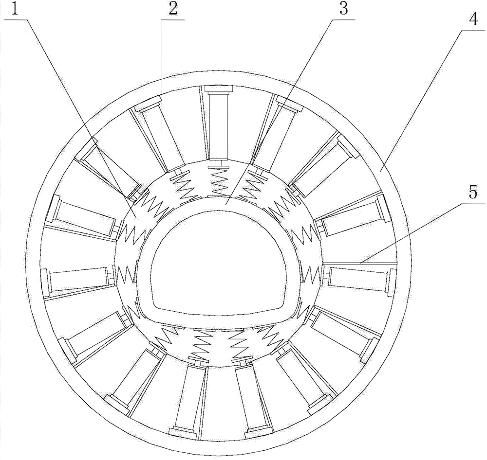
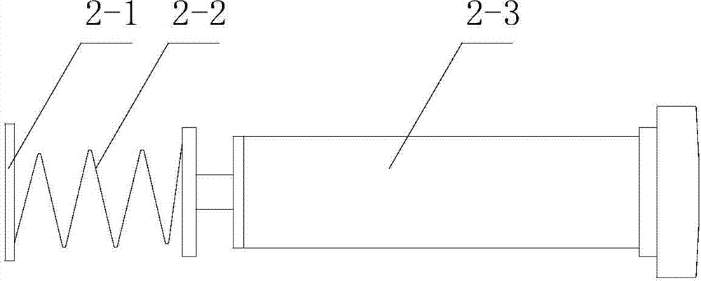
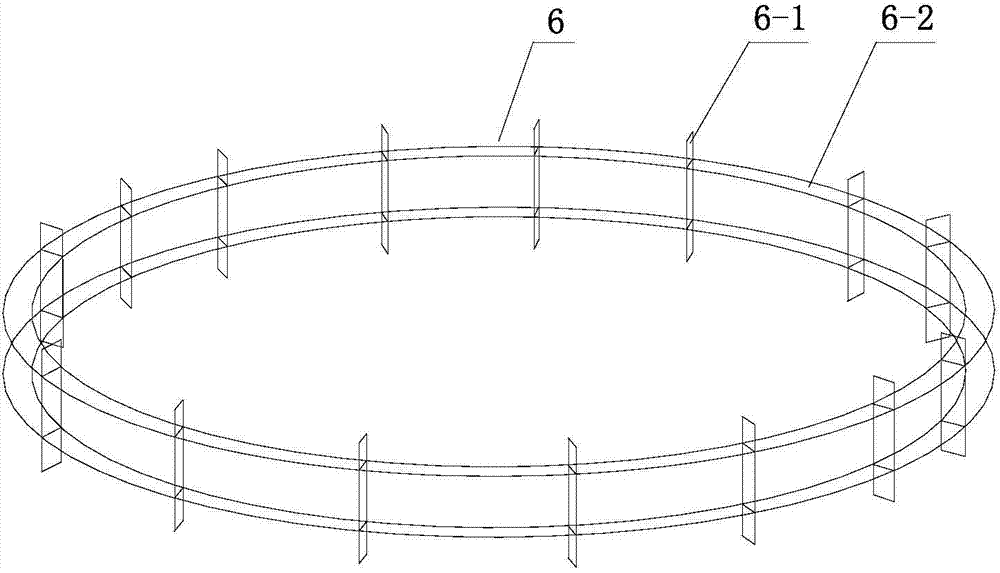
[0018] Such as figure 1 As shown, the loading equipment of the tunnel lining structure mechanical properties simulation test device in this embodiment is composed of a displacement limiting panel 1, a peripheral baffle plate 4, a gasket 2-1, a spring 2-2, a hydraulic jack 2-3, and a connecting support 5 1. The reinforcement steel ring 6-2 and the reinforcement rib 6-1 are connected to form.
[0019] The displacement limiting panel 1 of the present embodiment is a circular steel plate with a diameter of 150 cm and a thickness of 3 cm. A limiting groove is processed on the upper surface of the displacement limiting panel 1. The groove depth of the limiting groove is 3 cm, and the groove width is 6 cm. The shape is the same as the cross-sectional shape of the road tunnel lining 3, that is, the outline of the road tunnel lining 3, which can fix the road tunnel lining 3 in the limit groove, restricting the displacement of the bottom end of the tunnel lining 3 under the surrounding ...
Embodiment 2
[0028]The displacement limiting panel 1 of the present embodiment is a circular steel plate with a diameter of 150 cm and a thickness of 3 cm. A limiting groove is processed on the upper surface of the displacement limiting panel 1. The depth of the limiting groove is 4 cm, and the groove width is 6 cm. The shape is the same as the cross-sectional shape of the railway tunnel lining 3, that is, the outline of the railway tunnel lining 3, which can fix the railway tunnel lining 3 in the limit groove and limit the displacement of the bottom end of the railway tunnel lining 3 under the peripheral force. The edge of the displacement limiting panel 1 is fixedly installed with connecting supports 5 with threaded fasteners. The connecting supports 5 are arranged along the radial direction of the tunnel lining 3 and evenly distributed on the same circumference. The other end of the connecting supports 5 is fixed at the displacement The bottom edge of the peripheral baffle plate 4 on the...
Embodiment 3
[0031] In this embodiment, 18 steel spacers 2-1 are bonded with superglue on the outer wall of the tunnel lining 3, and a cylindrical protrusion is processed at the center of each spacer 2-1. The upper cover is equipped with a high-hardness stainless steel spring 2-2, and the spring 2-2 extends in the normal direction along the outer surface of the railway tunnel lining 3, and the other end of the spring 2-2 is connected with a hydraulic jack 2-3 through a connecting piece. The hydraulic jack 2-3 is also arranged along the normal direction of the outer surface of the railway tunnel lining 3, and the contact area between the gasket 2-1 and the lining is 3.5 times the area of the head of the jack. The cylinder barrel of the hydraulic jack 2-3 is fixedly installed on the inner wall of the peripheral baffle plate 4 through the connecting piece. The peripheral baffle plate 4 of the present embodiment is a ring plate with an inner diameter of 180cm, and its height is 1.5cm. The hyd...
PUM
 Abstract
Description
Claims
Application Information
 - R&D
- Intellectual Property
- Life Sciences
- Materials
- Tech Scout
- Unparalleled Data Quality
- Higher Quality Content
- 60% Fewer Hallucinations
Browse by: Latest US Patents, China's latest patents, Technical Efficacy Thesaurus, Application Domain, Technology Topic, Popular Technical Reports.
© 2025 PatSnap. All rights reserved.Legal|Privacy policy|Modern Slavery Act Transparency Statement|Sitemap|About US| Contact US: help@patsnap.com


