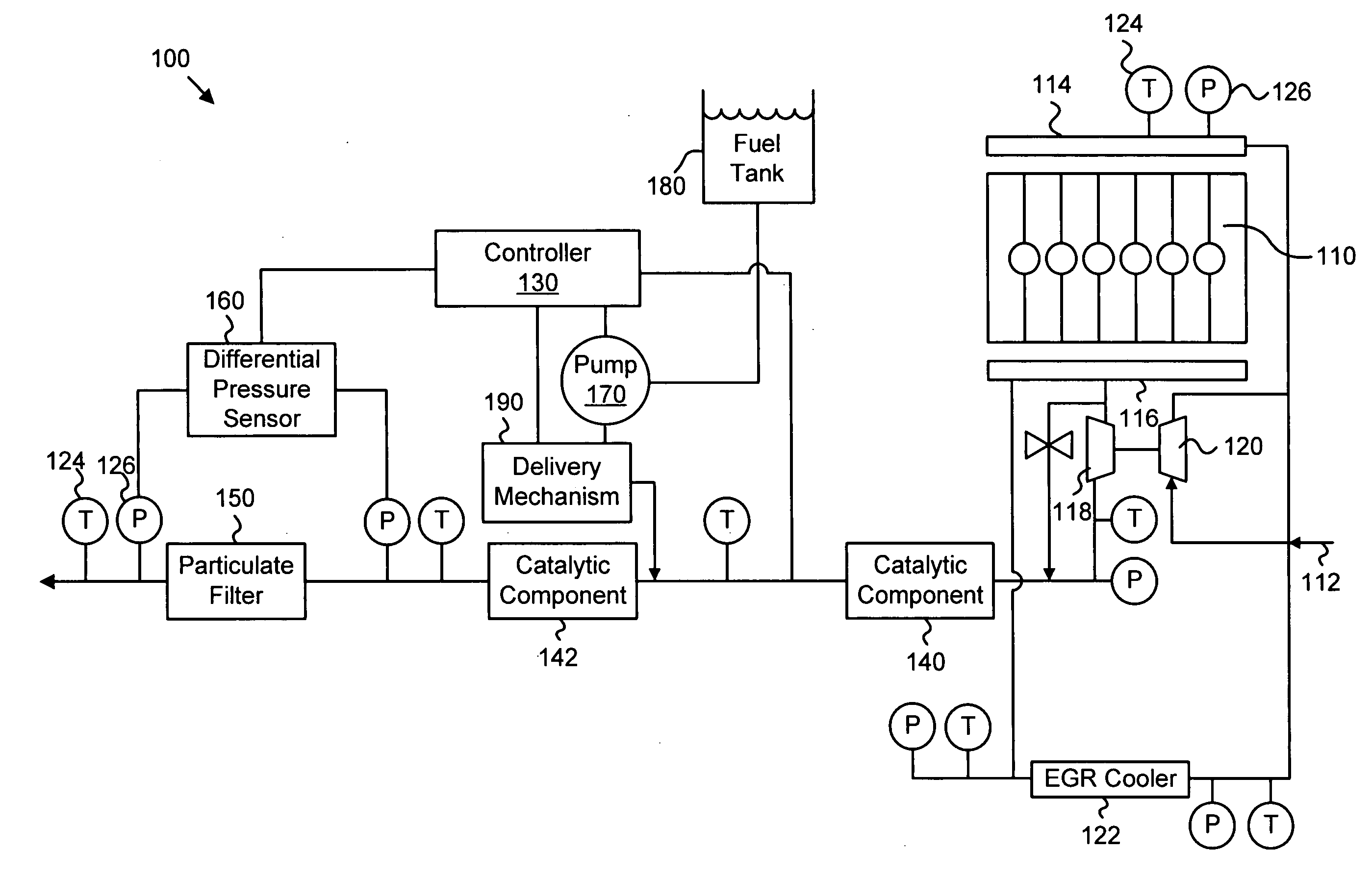
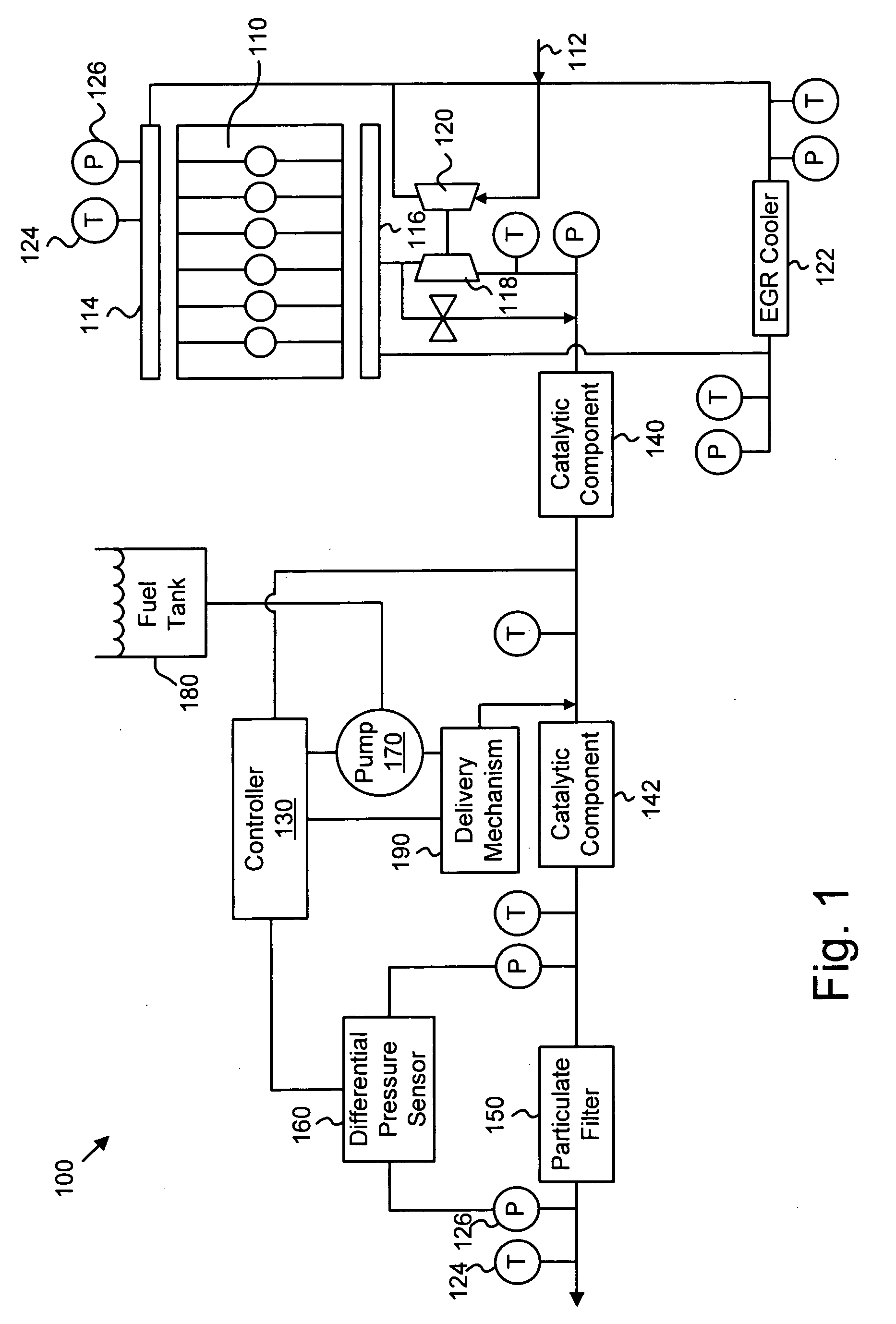
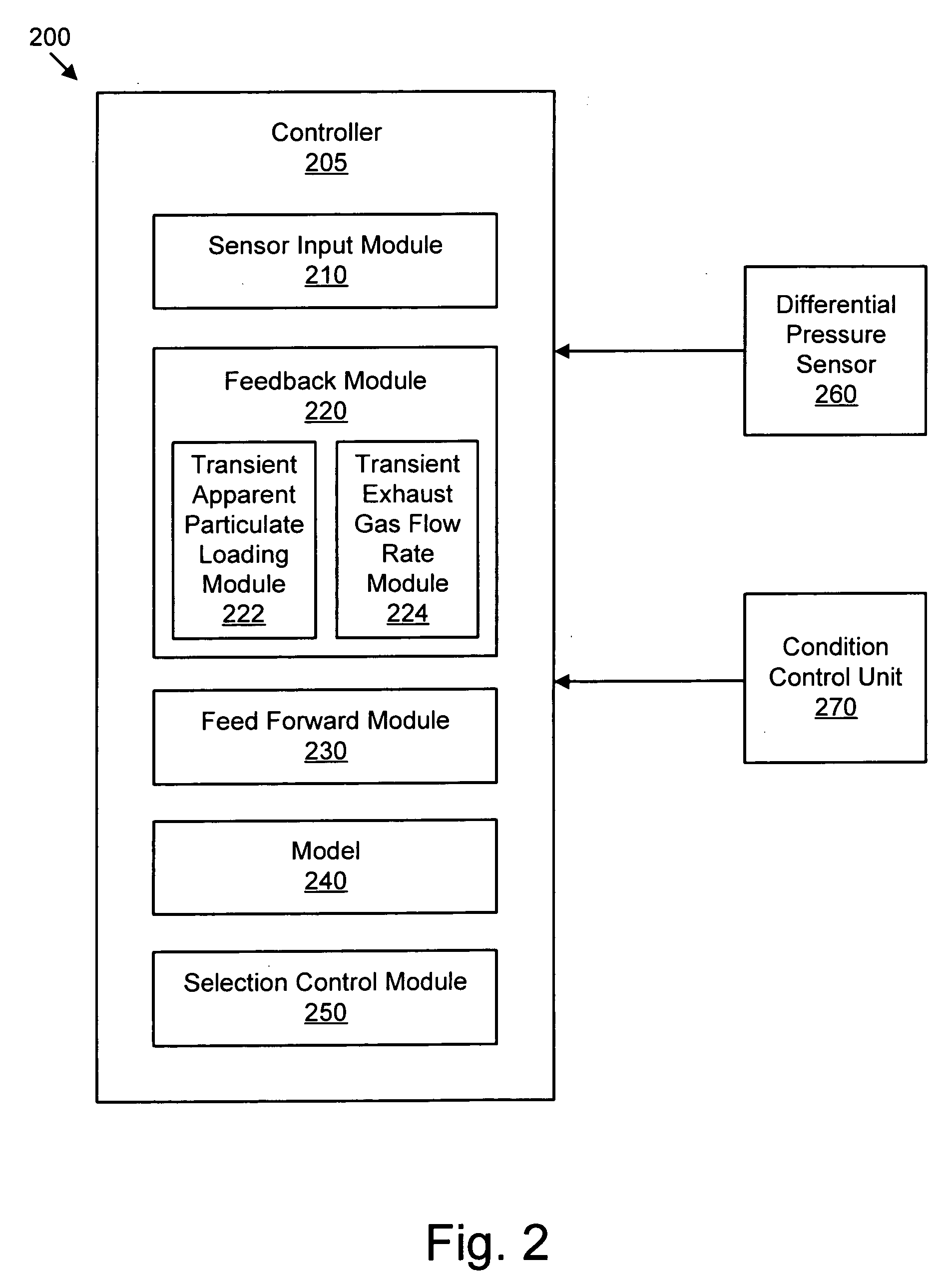
Apparatus, system, and method for determining the distribution of particulate matter on a particulate filter

a technology of particulate matter and filter, which is applied in the direction of mechanical equipment, non-fuel substance addition to fuel, machines/engines, etc., can solve the problems of uncontrolled temperature excursion, degrade engine performance, and incomplet fuel combustion, so as to facilitate the determination of accurate soot loading estimates and facilitate the determination of the effect of determining

Active Publication Date: 2007-03-15
CUMMINS INC
View PDF19 Cites 29 Cited by
  • Summary
  • Abstract
  • Description
  • Claims
  • Application Information

AI Technical Summary

Benefits of technology

[0016] In a further embodiment, the controller selectively combines the first particulate distribution with a particulate distribution trend derived from known operating conditions to determine a second particulate distribution. The d

Problems solved by technology

Soot, chiefly composed of carbon, results from incomplete combustion of fuel and generally comprises a large percentage of particulate matter buildup.
Accumulation of particulate matter typically causes backpressure within the exhaust system which can degrade engine performance.
If too much particulate matter has accumulated when oxidation begins, the oxidation rate may reach a point that it causes an uncontrolled temperature excursion.
The resulting heat can destroy the filter and damage surrounding structures.
Recovery can be an expensive process.
Irregular or non-uniform distribution contributes to errors in estimating the amount of particulate on the filter, among other problems.
Interval-based regeneration, however, has not proven to be totally effective for several reasons.
First, regenerating a particulate filter wi

Method used


Image

  • Apparatus, system, and method for determining the distribution of particulate matter on a particulate filter
  • Apparatus, system, and method for determining the distribution of particulate matter on a particulate filter
  • Apparatus, system, and method for determining the distribution of particulate matter on a particulate filter

Examples


Embodiment Construction

[0037] Many of the functional units described in this specification have been labeled as modules, in order to more particularly emphasize their implementation independence. For example, a module may be implemented as a hardware circuit comprising custom VLSI circuits or gate arrays, off-the-shelf semiconductors such as logic chips, transistors, or other discrete components. A module may also be implemented in programmable hardware devices such as field programmable gate arrays, programmable array logic, programmable logic devices or the like.

[0038] Modules may also be implemented in software for execution by various types of processors. An identified module of executable code may, for instance, comprise one or more physical or logical blocks of computer instructions which may, for instance, be organized as an object, procedure, or function. Nevertheless, the executables of an identified module need not be physically located together, but may comprise disparate instructions stored i...


PUM


Abstract

An apparatus, system, and method are disclosed for determining the distribution of particulate matter on a particulate filter. The apparatus, in one embodiment, determines a first distribution of particulate matter by comparing the pressure change across the particulate filter with a change in engine operating conditions. The apparatus may include an input module for receiving input corresponding to engine operating conditions and input from a differential pressure sensor and a feedback module to determine a first distribution of particulate matter. The apparatus may further include a feed forward module for determining a particulate distribution trend and a selection control module to combine the first distribution of particulate matter with the particulate distribution trend to determine a second distribution of particulate matter. The distribution may be defined as a uniform distribution factor in certain embodiments.

Description

BACKGROUND OF THE INVENTION [0001] 1. Field of the Invention [0002] This invention relates to exhaust gas after-treatment systems, and more particularly to apparatuses, systems and methods for determining the distribution of particulate matter on a particulate filter. [0003] 2. Description of the Related Art [0004] Environmental concerns have motivated the implementation of emission requirements for internal combustion engines throughout much of the world. Governmental agencies, such as the Environmental Protection Agency in the United States, carefully monitor the emission quality of engines and set acceptable emission standards, to which all engines must comply. Generally, emission requirements vary according to engine type. Emission tests for compression-ignition (diesel) engines typically monitor the release of diesel particulate matter, nitrogen oxides, and unburned hydrocarbons. Catalytic converters implemented in an exhaust gas after-treatment system have been used to elimina...

Claims


Application Information

Patent Timeline
IPC IPC(8): F01N3/00
CPCF01N3/035F01N13/009F01N9/002F01N9/005F01N9/007F01N11/002F01N2900/0421F02B37/00F02M25/0707F02M25/0727F02M25/0754Y02T10/144Y02T10/26Y02T10/47F01N13/0093F01N3/2033F02M26/05F02M26/23F02M26/47Y02T10/12Y02T10/40
Inventor BERRYHILL, ROSS C.CURRIER, NEAL W.WILLS, J. STEVEWILLS, JOANYEZERETS, ALEKSEY
Owner CUMMINS INC
Why Eureka
Try Eureka