Electronic buzzer

A buzzer, electronic technology, applied in the direction of instruments, sounding equipment, etc., can solve the problem of not clear enough sound, and achieve the effect of clear and ethereal sound and pleasant sound.

Pending Publication Date: 2019-02-01
江苏宏胜达电子科技有限公司
View PDF0 Cites 0 Cited by
  • Summary
  • Abstract
  • Description
  • Claims
  • Application Information

AI Technical Summary

Problems solved by technology

Due to the influence of the material of the vibrating diaphragm and other factors, the sound of the buzzer with the vibrating diaphragm is not clear enough. This is an important topic for technical research in the industry.

Method used


Image

  • Electronic buzzer

Examples


Embodiment Construction

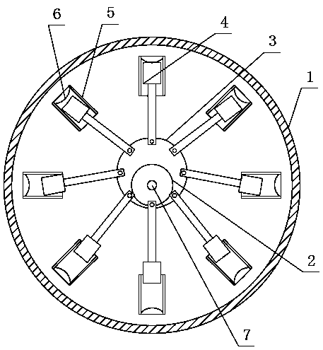
[0016] like figure 1 As shown: the electronic buzzer of this embodiment includes a housing 1, an electric motor 2 is arranged on the inner lower part of the housing, the power output shaft of the electric motor is eccentrically connected to the turntable 3, and the outer periphery of the turntable A group of striking hammers 4 are connected through a group of pin shafts, each of the striking hammers is provided with a guide cylinder 5, and each of the said guide cylinders is respectively provided with a metal diaphragm 6 inside.

[0017] In the electronic buzzer, a set of grooves is arranged inside the guide cylinder, and the metal diaphragm is plugged into one of the grooves. A set of grooves is set to adjust the position of the metal diaphragm according to the needs. When the distance between the diaphragm and the turntable is closer, the greater the impact force received during the hitting process, the greater the amplitude and the louder the sound will be. long.

[0018]...


PUM


Abstract

The invention provides an electronic buzzer. The electronic buzzer comprises a shell. The inner lower part of the shell is provided with an electric motor. The power output shaft of the electric motoris eccentrically connected with a turntable. The periphery of the turntable is connected with a set of hammers through a set of pins. Each hammer is provided with a guide cylinder, and each guide cylinder is internally provided with a metal diaphragm. The electronic buzzer can produce clear and crisp sounds and can achieve the effect of chord tone.

Description

Technical field: [0001] The invention relates to a buzzer, in particular to an electronic buzzer. Background technique: [0002] The buzzer is an electronic sounder with an integrated structure. It is powered by DC voltage and is widely used as a sounding device in electronic products such as computers, printers, copiers, alarms, electronic toys, automotive electronic equipment, telephones, and timers. . Buzzers are mainly divided into two types: piezoelectric buzzers and electromagnetic buzzers. The electromagnetic buzzer is composed of an oscillator, an electromagnetic coil, a magnet, a vibrating diaphragm and a casing. After the power is turned on, the audio signal current generated by the oscillator passes through the electromagnetic coil, causing the electromagnetic coil to generate a magnetic field. Under the interaction of the electromagnetic coil and the magnet, the vibrating diaphragm periodically vibrates and produces sound. Due to the influence of factors such...

Claims


Application Information

Patent Timeline
Patent Type & Authority Applications(China)
IPC IPC(8): G10K9/12G10K9/13G10K9/20
CPCG10K9/12G10K9/13G10K9/20
Inventor 刘创辉
Owner 江苏宏胜达电子科技有限公司
Why Eureka
Try Eureka