PCB connector and PCB connection structure

A technology of PCB board and connection structure, applied in the direction of connection, fixed connection, electrical components, etc., can solve the problems of no anti-reverse insertion, trouble for designers, height restrictions, etc., to ensure the quality of signal transmission and avoid interference.

Pending Publication Date: 2019-02-01
GREE ELECTRIC APPLIANCES INC OF ZHUHAI
View PDF0 Cites 1 Cited by
  • Summary
  • Abstract
  • Description
  • Claims
  • Application Information

AI Technical Summary

Problems solved by technology

[0007] 1. It does not have the function of anti-reverse insertion and pre-alignment, which will cause great difficulties for the connection of the top PCB board;
[0008] 2. The pin row is thinner, and the height will also be limited. Generally, when the pin row height is greater than 55mm, it is easy to bend;
[0009] 3. It is difficult to solve the problem that the signal is easily interfered in the transmission of sensitive signals;
[0010] 4. Using a simple pin row as the connection structure will affect the structural arrangement of the controller and the safety distance, which will bring great trouble to the designer

Method used


Image

  • PCB connector and PCB connection structure
  • PCB connector and PCB connection structure
  • PCB connector and PCB connection structure

Examples


Embodiment 1

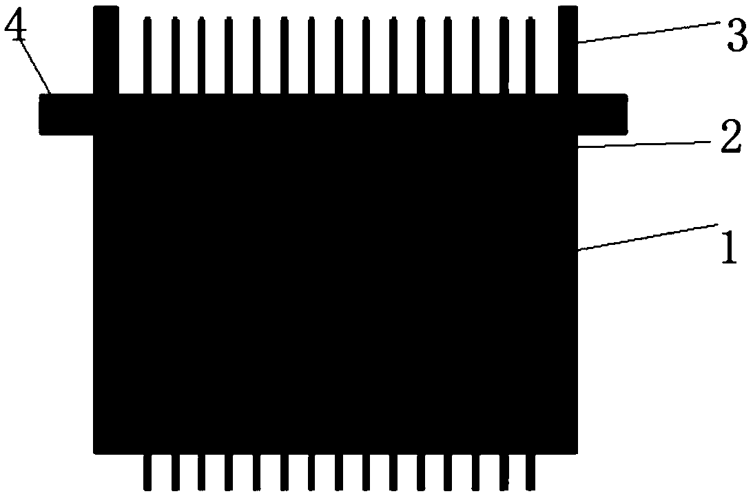
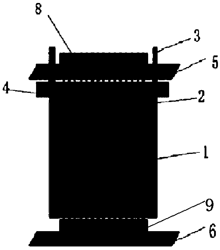
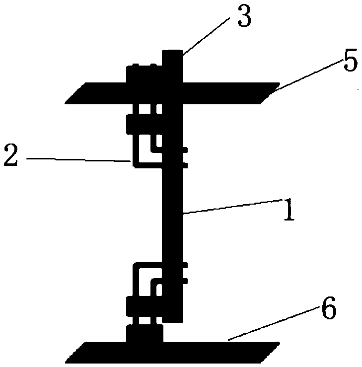
[0038] The PCB board connector proposed by the present invention is used for the connection between PCB boards, including L-shaped pin header 2 and PCB adapter board 1, the upper and lower ends of PCB adapter board 1 are equipped with L-shaped pin header 2, L-shaped One end of pin 2 is inserted into the jack on the PCB adapter 1 to fix it, and the other end protrudes out of the PCB adapter board 1 for connection with an external PCB board (such as image 3 shown). For more sensitive transmission signals, choose to ground the PCB adapter board with copper clad to ensure the quality of signal transmission.

[0039] Since short L-shaped pin headers 2 are used up and down, there is one row at the upper and lower ends of the pin header 2, and the height between the upper and lower rows of pin headers 2 is determined by the PCB adapter board 1. Since the L-shaped pin header 2 is relatively short, The needle row 2 can withstand a large force when pulling out, and the needle will not...

Embodiment 2

[0045] The PCB board connector proposed by the present invention is used for the connection between PCB boards, including L-shaped pin header 2 and PCB adapter board 1, the upper and lower ends of PCB adapter board 1 are equipped with L-shaped pin header 2, L-shaped One end of pin 2 is inserted into the jack on the PCB adapter 1 to fix it, and the other end protrudes out of the PCB adapter board 1 for connection with an external PCB board (such as image 3 shown). For more sensitive transmission signals, choose to ground the PCB adapter board with copper clad to ensure the quality of signal transmission.

[0046] Since short L-shaped pin headers 2 are used up and down, there are two rows of pin headers 2 up and down, and there are rows of pin header jacks 10 on the PCB adapter board 1. The lengths of the two ends of the L-shaped pin header 2 can be inserted into the PCB adapter. Among the different pin headers 10 of the connecting board 1, the farther the row hole is from the...


PUM


Abstract

The invention, which belongs to the PCB field, provides a PCB connector and a PCB connection structure. The PCB connector comprises a PCB adapter board and L-shaped short-row pins. The pin part is installed and fixed partially at the upper and lower end portions of the PCB adapter board; and positioning columns for positioning and bosses for installing a PCB conveniently are arranged at one end portion of the PCB adapter board. The PCB adapter board carries out ground copper cladding based on needs to realize shielding, so that the signal is protected from being affected and the signal transmission quality is ensured. According to the invention, on the basis of combination of the PCB adapter board and the d L-shaped short-row pins, problems that the connection height and routing are limited between the PCBs are solved; with the copper cladding of the PCB, the signal is protected from being affected; and with the positioning columns, the pre alignment function is realized and thus connector pins are protected from being damaged.

Description

technical field [0001] The invention relates to the field of PCB boards, in particular to a PCB board connector and a PCB board connection structure. Background technique [0002] PCB board (Printed Circuit Board), the Chinese name is printed circuit board, referred to as printed board, is one of the important components of the electronics industry. The insulating board is used as the base material, cut to a certain size, with at least one conductive pattern on it, and holes (such as component holes, fastening holes, metallized holes, etc.), used to replace the chassis of the previous electronic components , and realize the interconnection between electronic components. Since such boards are made using electronic printing, they are called "printed" circuit boards. [0003] my country's PCB manufacturing industry is developing rapidly, and its total output value and total output both rank first in the world. Due to the ever-changing electronic products, the price war has c...

Claims


Application Information

Patent Timeline
IPC IPC(8): H01R12/58H01R31/06
CPCH01R12/58H01R31/06
Inventor 黄伟庭刘亚祥经琦王长恺樊柳芝贾卫东黄男
Owner GREE ELECTRIC APPLIANCES INC OF ZHUHAI
Why Eureka
Try Eureka