
A plug pin pressing and positioning device through sliding fixation and hydraulic balance

A technology of hydraulic balance and positioning device, which is applied in the direction of coupling device, two-part connecting device, and parts of connecting device, etc., can solve the problems of tripping on the power line, burning, fire, etc., and achieve the effect of smooth power supply

Active Publication Date: 2019-11-22
泰安泰山科技有限公司
View PDF3 Cites 0 Cited by
  • Summary
  • Abstract
  • Description
  • Claims
  • Application Information

AI Technical Summary

Problems solved by technology

[0003] Aiming at the deficiencies in the prior art, the purpose of the present invention is to provide a plug pin pressing and positioning device through sliding fixation and hydraulic balance, so as to solve the problem of pets playing on the floor and tripping over the power cord if they do not pay attention. When the pins and the socket are disconnected, the electrical appliance will stop running. When the plug pins and the socket are half-disconnected, there will be a short circuit at the connection between the plug pins and the socket, which will cause the socket to heat up or burn, and even cause a fire.

Method used


Image

  • A plug pin pressing and positioning device through sliding fixation and hydraulic balance
  • A plug pin pressing and positioning device through sliding fixation and hydraulic balance
  • A plug pin pressing and positioning device through sliding fixation and hydraulic balance

Examples


Embodiment Construction

[0024] In order to make the technical means, creative features, goals and effects achieved by the present invention easy to understand, the present invention will be further described below in conjunction with specific embodiments.

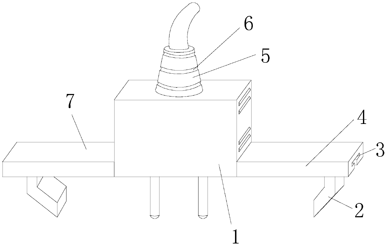
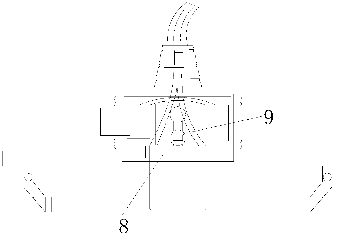
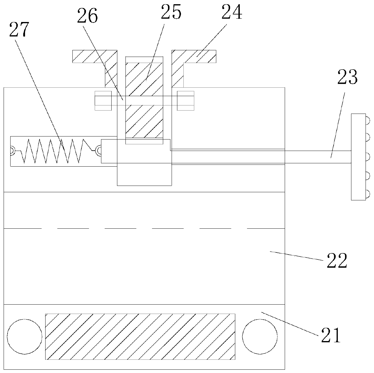
[0025] see Figure 1-Figure 2 , the present invention provides a plug pin pressing and positioning device through sliding fixation and hydraulic balance: its structure includes a fixed shell 1, a sliding self-locking device 2, a chute 3, a right horizontal plate 4, an anti-twist sleeve 5, a groove 6. Left horizontal plate 7, hydraulic balance movable pin device 8, power cord 9, said right horizontal plate 4 is welded on the lower end of the right surface of fixed shell 1, said chute 3 is embedded in the inside of right horizontal plate 4, so The upper end of the sliding self-locking device 2 is in clearance fit with the chute 3, the anti-twist sleeve 5 is glued to the upper end of the fixed shell 1, the groove 6 is embedded in the outer ring of th...


PUM


Abstract

The invention discloses a plug pin pressing and positioning device based on sliding fixation and hydraulic pressure balance. The structure of the device comprises a fixing shell, a sliding self-locking devices, sliding slots, a right horizontal plate, an anti-torsion sleeve, a groove, a left horizontal plate, a hydraulic pressure balance movable pin device and a power source line. The sliding self-locking device is adopted; a lower suction cup and a rubber pad are matched with each other so as to initially fix a corresponding positioning adsorption structure; a pressing clamping buckle and a spur gear are matched with each other, so that the self-locking position of the positioning adsorption structure can be adjusted; and the positioning adsorption structure is unlikely to slide. The hydraulic pressure balance movable pin device is adopted; a pressurization structure and a sliding fastening structure are matched with each other, so that a special-shaped fixing column has two connection states, namely, a clearance fit state and an interference fit state; in the insertion and removal process of pins, the special-shaped fixing column is in interference fit with the sliding fasteningstructure; and during the energization process of the pins, the special-shaped fixing column is in clearance fit with the sliding fastening structure.

Description

technical field [0001] The invention is a plug and socket device, in particular to a plug pin pressing and positioning device through sliding fixation and hydraulic balance. Background technique [0002] Generally, the connectors of electronic products and the pins of electrical appliances are collectively referred to as plugs, such as household plugs and sockets. There are two or three rod-shaped or sheet-shaped objects under the plug, which we call plug pins. When using electrical appliances, The plug needs to be connected to the socket. The back end of the plug is the power cord, and the power cord is often on the ground. When there are pets at home, there will be a problem; pets play on the floor, and they will trip over the power cord if they are not careful. When the pins of the plug and the socket are disconnected, the electrical appliance will stop running. When the pins of the plug and the socket are half disconnected, a short circuit will occur at the connection be...

Claims


Application Information

Patent Timeline
Patent Type & Authority Patents(China)
IPC IPC(8): H01R24/28H01R13/639
CPCH01R13/639H01R24/28
Inventor 庄明章
Owner 泰安泰山科技有限公司
Learn More