
Support assembly for the screw of a decanter screw centrifuge

A support and centrifuge technology, which is applied to centrifuges, centrifuges with rotating drums, bearings for rotating motion, etc., and can solve problems such as failure of a single axial support

Active Publication Date: 2021-06-11
FLOTTWEG GMBH & CO KGAA
View PDF5 Cites 0 Cited by
  • Summary
  • Abstract
  • Description
  • Claims
  • Application Information

AI Technical Summary

Problems solved by technology

[0003] Although such a bearing arrangement with several axial bearings can absorb higher axial forces in total than a single axial bearing, it can nonetheless be possible that the individual axial bearings of the bearing arrangement support becomes ineffective

Method used


Image

  • Support assembly for the screw of a decanter screw centrifuge
  • Support assembly for the screw of a decanter screw centrifuge
  • Support assembly for the screw of a decanter screw centrifuge

Examples


Embodiment Construction

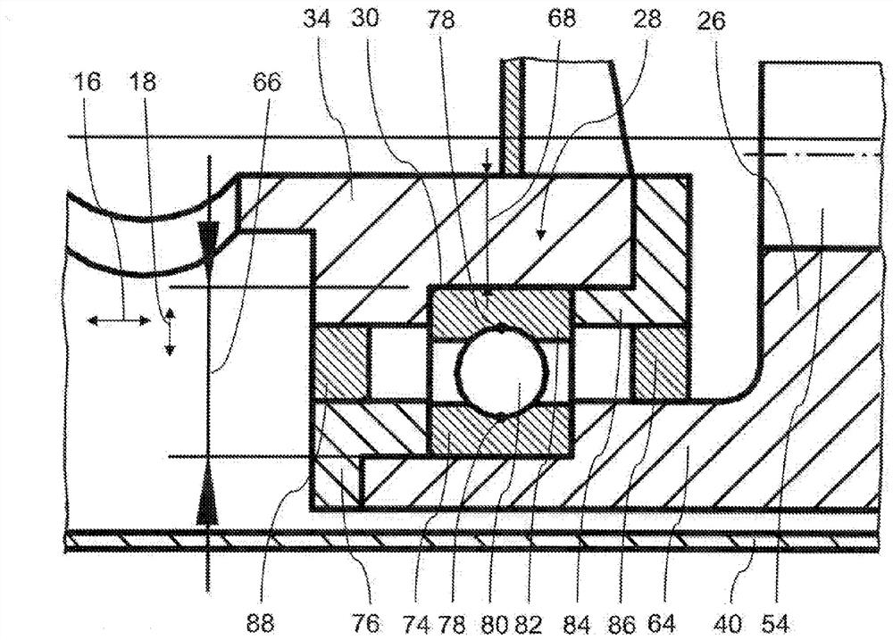
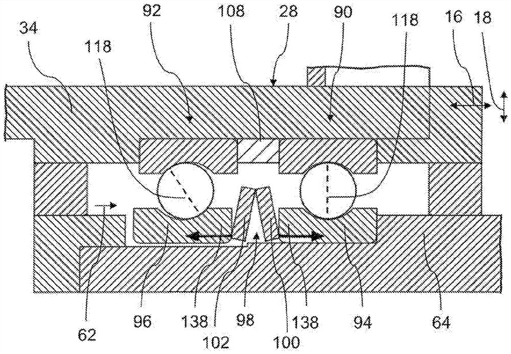
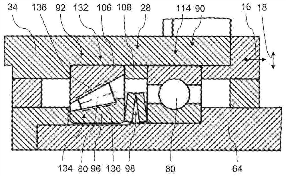
[0031] figure 1 A decanter screw centrifuge 10 is shown with its hollow cylindrical centrifuge barrel 14 rotatable about a centrifuge axis 12 . The centrifuge axis 12 defines an axial direction 16 and a radial direction 18 . The centrifuge cylinder 14 is surrounded by a housing 20 and is supported at its two axial end regions by means of a first cylinder support 22 and a second cylinder support 24 . The first bowl support 22 supports the centrifuge bowl 14 at a bowl cover 26 . The bowl cover 26 itself supports the screw 32 in the centrifuge bowl 14 by means of a bearing assembly 28 . The bearing arrangement 28 is designed as an axial bearing 30 .

[0032] The screw 32 comprises a substantially hollow-cylindrical screw hub 34 and a screw helix 36 which surrounds the screw hub radially on the outside. The screw hub 34 is rotatably supported on the centrifuge barrel at its one axial end region by means of the bearing arrangement 28 and at its other axial end region by means o...


PUM


Abstract

In the bearing assembly of the screw of the decanter screw centrifuge (which has a centrifuge axis, a first axial support and a second axial support, the first and second axial supports are arranged elastic means are provided for absorbing the axial force of the screw rod, and the second axial bearing is supported on the elastic means in the axial direction in order to support the axial force of the screw rod.

Description

technical field [0001] The invention relates to a support assembly for a screw of a decanter screw centrifuge (Vollmantelschneckenzentrifuge), with a centrifuge axis, a first axial support and a second axial support, in particular a bearing point, the first axial support and a second axial support arranged to absorb axial forces of the screw. Background technique [0002] Decanter screw centrifuges (also known as decanter centrifuges) continuously separate, in most cases, a flowable substance mixture into a light and a heavy phase ( Phase). The heavy phase is displaced within the barrel by a screw in the conveying direction to the end region of the barrel. To this end, the screw is located in the barrel and likewise rotates about the centrifuge axis. The screw rotates at a differential speed relative to the barrel speed. In the event of a displacement of the heavy phase in the conveying direction, axial forces act against the conveying direction. The axial force is abso...

Claims


Application Information

Patent Timeline
Patent Type & Authority Patents(China)
IPC IPC(8): B04B9/12B04B3/04B04B1/20
CPCB04B1/20B04B9/12F16C27/06
Inventor B.菲尔胡贝尔
Owner FLOTTWEG GMBH & CO KGAA
Learn More