
Ignition coil

A technology for ignition coils and connecting wires, which is applied in the direction of engine ignition, spark ignition controllers, spark plugs, etc., can solve the problems of non-realization of ignition feedback and high cost, and achieve the effects of low cost, guaranteed input, and friendly assembly

Inactive Publication Date: 2013-07-24
ROBERT BOSCH GMBH
View PDF5 Cites 1 Cited by
  • Summary
  • Abstract
  • Description
  • Claims
  • Application Information

AI Technical Summary

Problems solved by technology

Known ignition coils have in common that the feedback of the modules regarding the occurrence of ignition is either not realized at all or only through relatively complex measures or components, which entails high costs

Method used


Image

  • Ignition coil
  • Ignition coil
  • Ignition coil

Examples


Embodiment Construction

[0026] An ignition coil 1 according to a first embodiment of the present invention and a method of manufacturing the same will be described below with reference to FIGS. 1 and 2 .

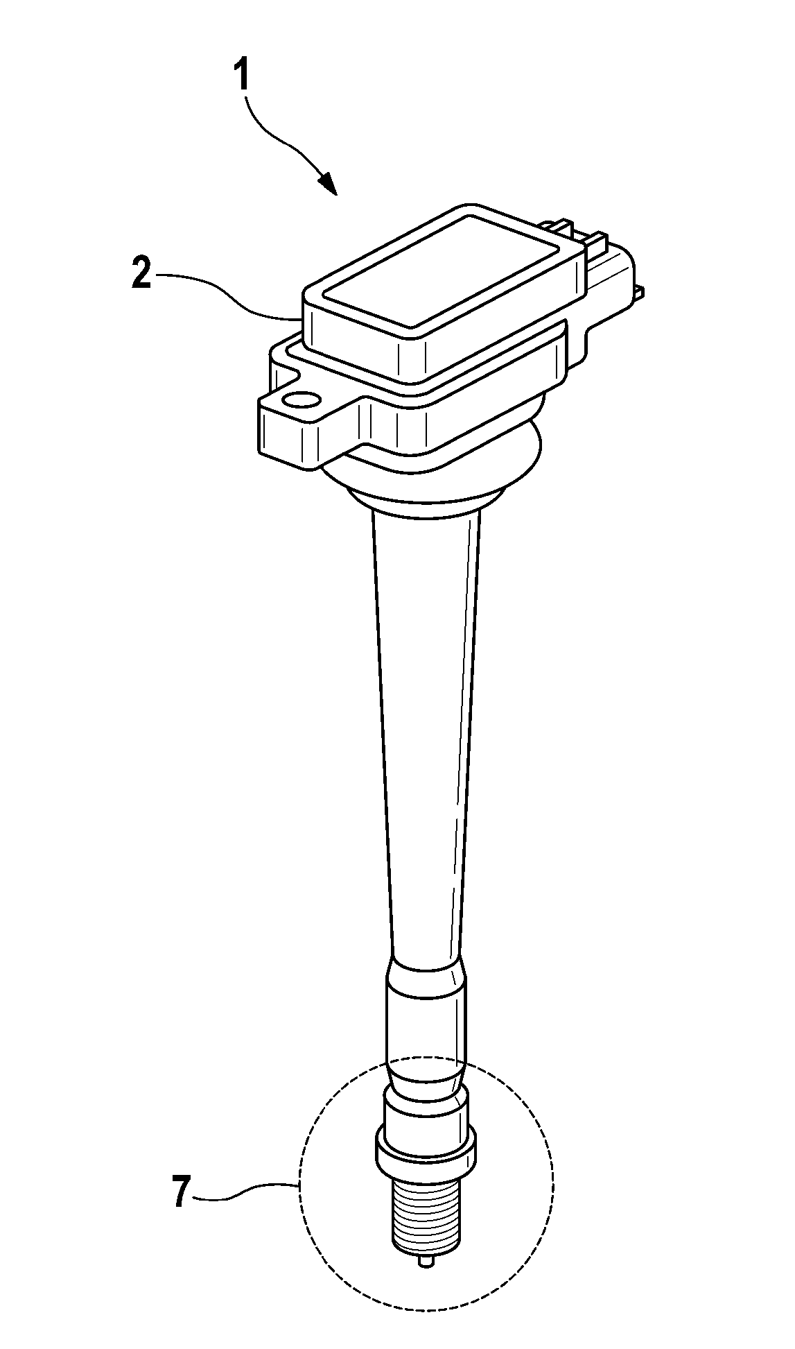
[0027] FIG. 1 shows a perspective external view of an ignition coil 1 according to the invention. A housing 2 is arranged on top of the drawing, in which housing the winding components are arranged. The housing 2 is substantially made of plastic, the properties of which are suitable for the operating conditions when used in a motor vehicle. Arranged below the housing is a rod which terminates on the bottom side with a spark plug connection 7 .

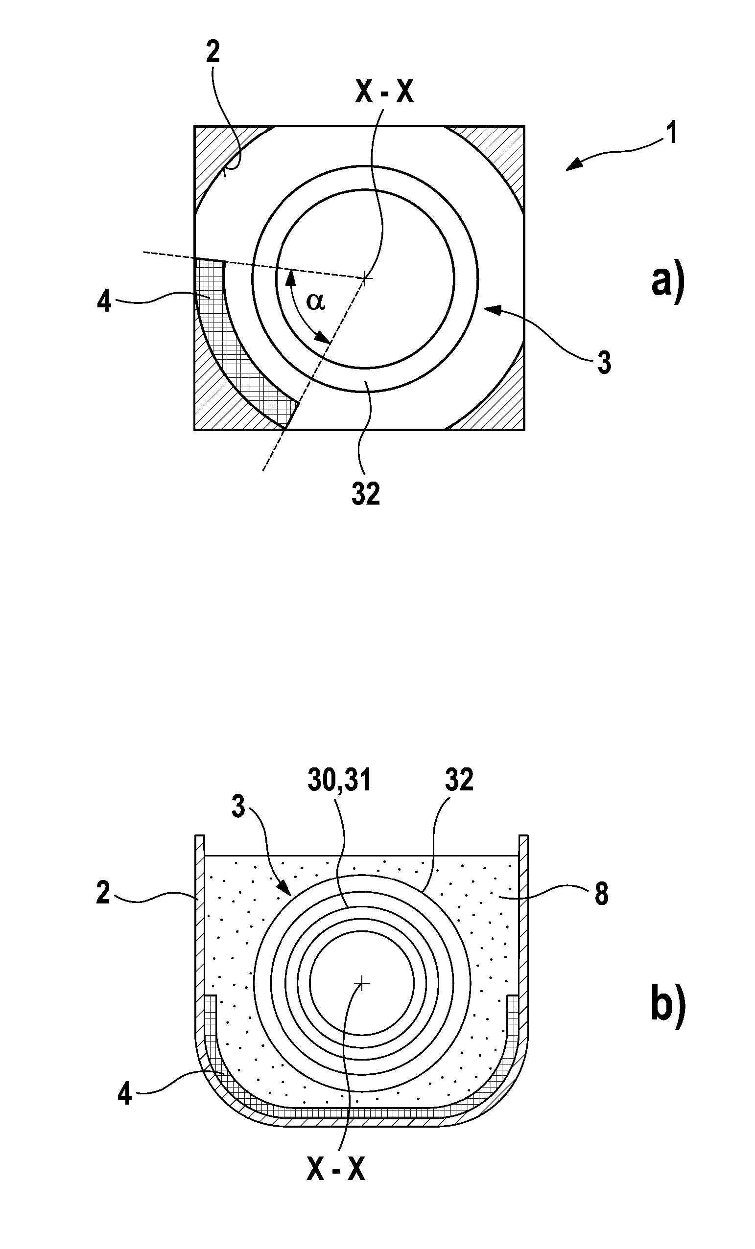
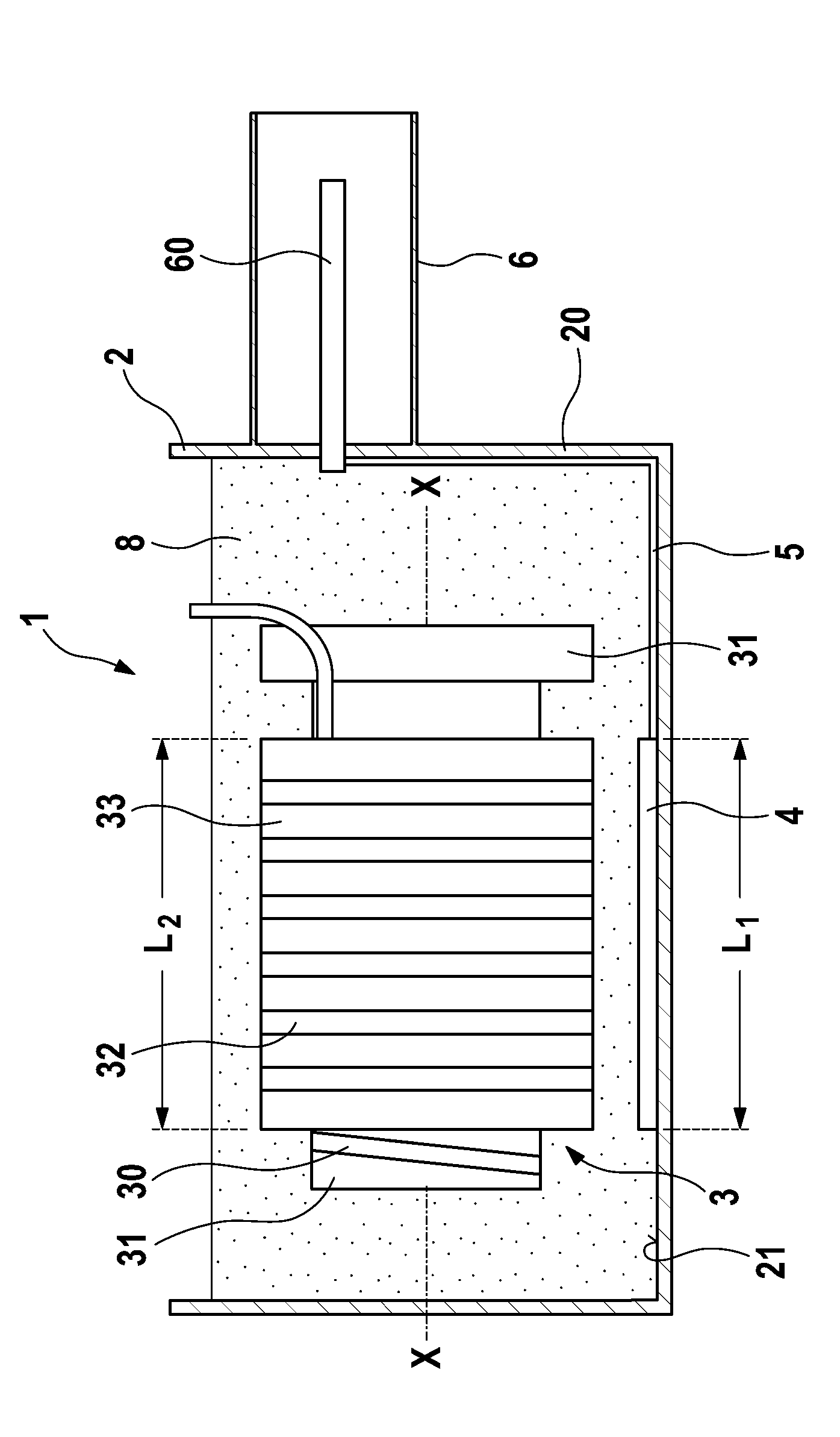
[0028] FIG. 2 shows an internal view of the housing 2 of the ignition coil 1 . Arranged inside the housing 2 is a winding part 3 , which on its outer side has a secondary winding 32 inserted into a secondary winding carrier 33 . In the secondary winding carrier 33 , the primary winding 30 is inserted coaxially into the primary winding carrier 31 . Prefe...


PUM


Abstract

The invention relates to an ignition coil (1) for an internal combustion engine, comprising: a housing (2) made in particular of plastics material, a winding assembly (3) having a primary winding (30) and a secondary winding (32), and an ignition sensor (4) for detecting an ignition, wherein the ignition sensor (4) is arranged adjacent to the secondary winding (32) on a wall (20), in particular an inner wall (21), of the housing (2).

Description

technical field [0001] The invention relates to an ignition coil for an internal combustion engine and a method for producing the ignition coil. In particular, the invention relates to a device in an ignition coil for detecting the occurrence of ignition. Background technique [0002] Ignition coils are used in internal combustion engines to ignite combustible (air mixture) gases at a predetermined point in time. For this purpose, electrodes which are arranged at a certain distance from one another are usually arranged in the combustion chamber and are acted upon by the ignition coil at predetermined points in time with a potential difference by which the ignition spark strikes between the electrodes. free distance between and ignite (mix) the gases there. It is assumed below that the working principle and function of the primary and secondary windings in the ignition coil for generating the required voltage pulses are known. The known ignition coils have in common that t...

Claims


Application Information

Patent Timeline
Patent Type & Authority Applications(China)
IPC IPC(8): H01F27/40H01F38/12F02P17/12
CPCH01F27/40H01F38/12F02P17/12F02P17/00H01T13/00H01F27/02
Inventor M.迈尔K.里斯米勒N.豪特曼
Owner ROBERT BOSCH GMBH
Learn More