Wind energy dust removal equipment

A technology of dust removal equipment and wind energy, which is applied to the separation of dispersed particles, chemical instruments and methods, and filtration of dispersed particles, which can solve the problems of power consumption, power consumption, and labor, and achieve the effects of preventing dust from clogging and saving power

Active Publication Date: 2019-02-12
南京勤丰秸杆科技有限公司
View PDF2 Cites 2 Cited by
  • Summary
  • Abstract
  • Description
  • Claims
  • Application Information

AI Technical Summary

Problems solved by technology

[0002] Dust removal equipment is often placed in some factories or in dusty working environments, but most of the dust removal equipment currently in use consumes electricity. The replacement of the board requires manual operation, which is very laborious, so this wind energy dust removal equipment is designed

Method used


Image

  • Wind energy dust removal equipment
  • Wind energy dust removal equipment
  • Wind energy dust removal equipment

Examples


specific Embodiment approach 1

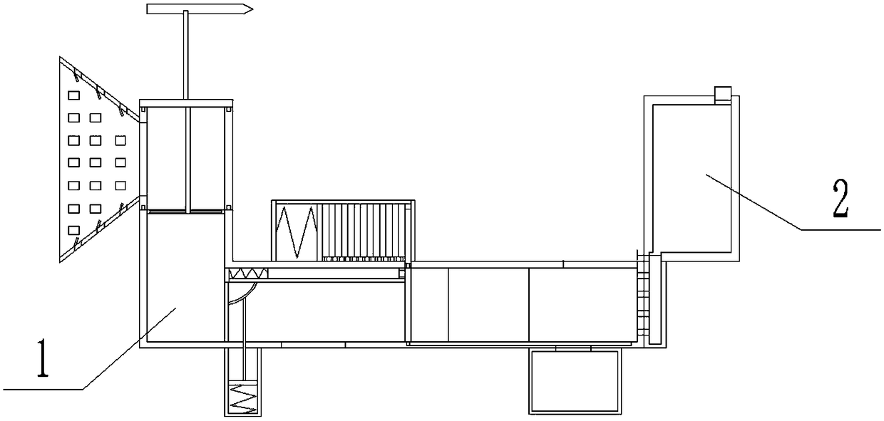
[0033] Combine below figure 1 , 2 , 3, 4, 5, 6, 7, 8, 9, 10, 11, 12 illustrate this embodiment, the present invention relates to a kind of dust removal equipment, more specifically a kind of wind energy dust removal equipment, including dust removal device 1, storage The water tank Ⅰ2 can not only remove dust through wind energy and save electricity, but also can automatically replace the filter plate to prevent the filter plate from being blocked by dust and affect the dust removal effect.

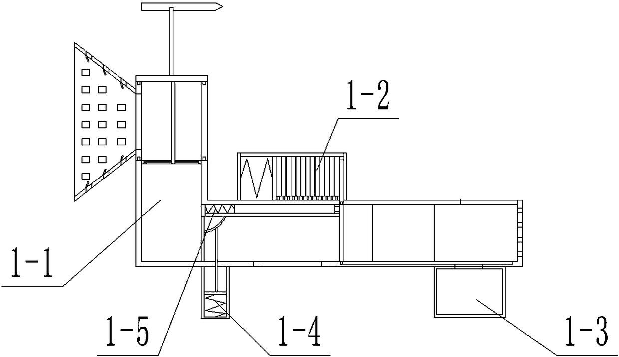
[0034] The dust removal device 1 is composed of a casing 1-1, a pushing device 1-2, a water storage tank II 1-3, a cleaning device 1-4, and a blocking device 1-5; the upper end of the casing 1-1 is provided with a pushing device 1-2 ; The cleaning device 1-4 and the water storage tank II 1-3 are all arranged at the lower end of the casing 1-1; the blocking device 1-5 is arranged inside the casing 1-1;

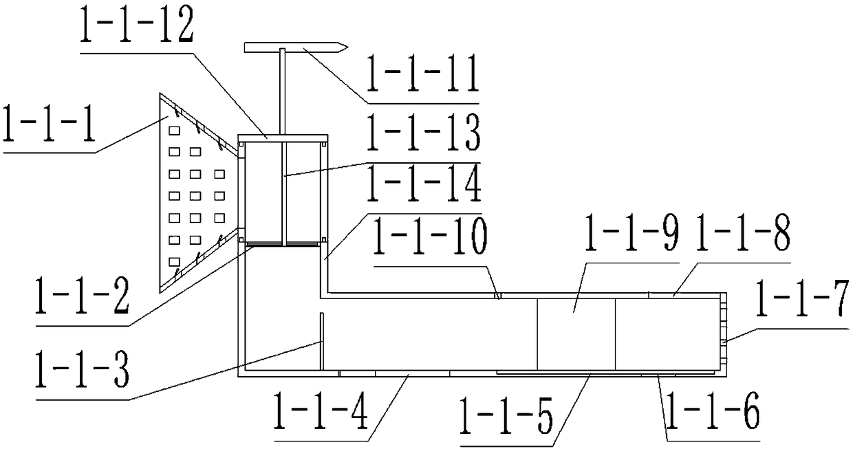
[0035]The housing 1-1 consists of a rotating device 1-1-1, a fan blade 1-1-2, a filt...

specific Embodiment approach 2

[0044] Combine below figure 1 , 2 , 3, 4, 5, 6, 7, 8, 9, 10, 11, 12 illustrate this embodiment, and this embodiment will further describe Embodiment 1, and the inclined baffles 1-1-1-5 are all directed to the holes Ⅰ The direction of 1-1-1-2 is inclined.

specific Embodiment approach 3

[0045] Combine below figure 1 , 2 . When Ⅰ1-1-5 moves to the position of the air outlet 1-1-9, the spring force of the spring Ⅲ1-5-2 is greater than the magnetic force between the magnet 1-5-5 and the filter plate Ⅱ1-2-5.

[0046]The working principle of the present invention is: when using this device to remove dust, the wind direction is determined by the wind vane 1-1-11, and then the rotating cylinder 1-1-1-1 is rotated so that the wind flows from the conical cylinder 1-1-1-3 and Hole II 1-1-1-4 enters the drum 1-1-1-1, and then pushes the fan blade 1-1-2 to rotate, so that the fan blade 1-1-2 drives the air to move in the main body of the housing 1-1-14 , when the wind moves to the position of the filter plate Ⅰ1-1-3, it is filtered through the filter plate Ⅰ1-1-3 to prevent the dust in the air from entering the right side of the filter plate Ⅰ1-1-3, and the wind blows horizontally through the air inlet 1- 1-4 Reduce the pressure on the upper end of the air inlet 1-1-4...


PUM


Abstract

The invention relates to dust removal equipment, in particular to wind energy dust removal equipment, which not only can be used for removing dust by means of wind energy so as to save electric energy, but also can automatically replace a filter plate so as to prevent a dust removing effect from being affected since the filter plate is blocked by dust. A push device is arranged at the upper end ofa shell; a cleaning device and a water storage tank II are arranged at the lower end of the shell; a blocking device is arranged in the shell; one end of a spring III is fixedly connected with a fixed plate, and the other end of the spring III is fixedly connected with a board; a magnet is arranged at the right end of the board; the fixed plate is fixedly connected with the interior of a main body of the shell, and is positioned at the upper end of a filter plate I; the magnet attracts a filter plate II; a water storage tank I consists of a main body of the water storage tank I, a plug, a valve and a through hole IV; the plug is arranged at the upper end of the main body of the water storage tank I; the valve is arranged on the main body of the water storage tank I; the through hole IV isformed at the left lower left end of the main body of the water storage tank I.

Description

technical field [0001] The invention relates to a dust removal device, more specifically to a wind energy dust removal device. Background technique [0002] Dust removal equipment is often placed in some factories or in dusty working environments, but most of the dust removal equipment currently in use consumes electricity. The replacement of the plate requires manual operation, which is very laborious, so this wind energy dust removal equipment is designed. Contents of the invention [0003] The invention provides a wind energy dedusting device, which has the beneficial effect that not only can the dust be removed by the wind energy, save electric energy, but also can automatically replace the filter plate, preventing the filter plate from being blocked by dust and affecting the dust removal effect. [0004] In order to solve the above technical problems, the present invention relates to a dust removal equipment, more specifically a wind energy dust removal equipment, in...

Claims


Application Information

Patent Timeline
Patent Type & Authority Applications(China)
IPC IPC(8): B01D46/12B01D46/00
CPCB01D46/0008B01D46/12B01D46/88
Inventor 林雯臻
Owner 南京勤丰秸杆科技有限公司
Why Eureka
Try Eureka