Automatic assembling equipment of self-buckling type pipe clamp, nut and screw

An automatic assembly and self-fastening technology, which is applied in metal processing equipment, assembly machines, manufacturing tools, etc., can solve the problems of manual picking and placing of raw materials, low assembly efficiency, easy hand injury, etc., to reduce work-related injuries, improve production efficiency, Labor saving effect

Pending Publication Date: 2019-02-12
湖南湘光机械模具有限公司
View PDF0 Cites 1 Cited by
  • Summary
  • Abstract
  • Description
  • Claims
  • Application Information

AI Technical Summary

Problems solved by technology

However, both of these methods require manual picking and placing of raw materials, resulting in low assembly efficiency
[0004] The self-locking pipe clip is a new type of pipe clip structure that uses a rotating hook on one side and a nut on the other side to fix it; at present, it mainly relies on manual use of a small hammer to hit the hook and the nut by hand, and then manually screw it in. The screw is screwed into the nut for assembly, the operation is cumbersome, the assembly efficiency is very low, and it is easy to hurt the hand

Method used


Image

  • Automatic assembling equipment of self-buckling type pipe clamp, nut and screw
  • Automatic assembling equipment of self-buckling type pipe clamp, nut and screw
  • Automatic assembling equipment of self-buckling type pipe clamp, nut and screw

Examples


Embodiment Construction

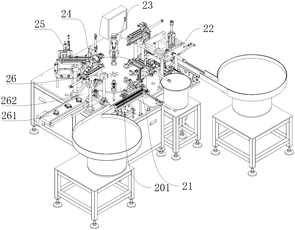
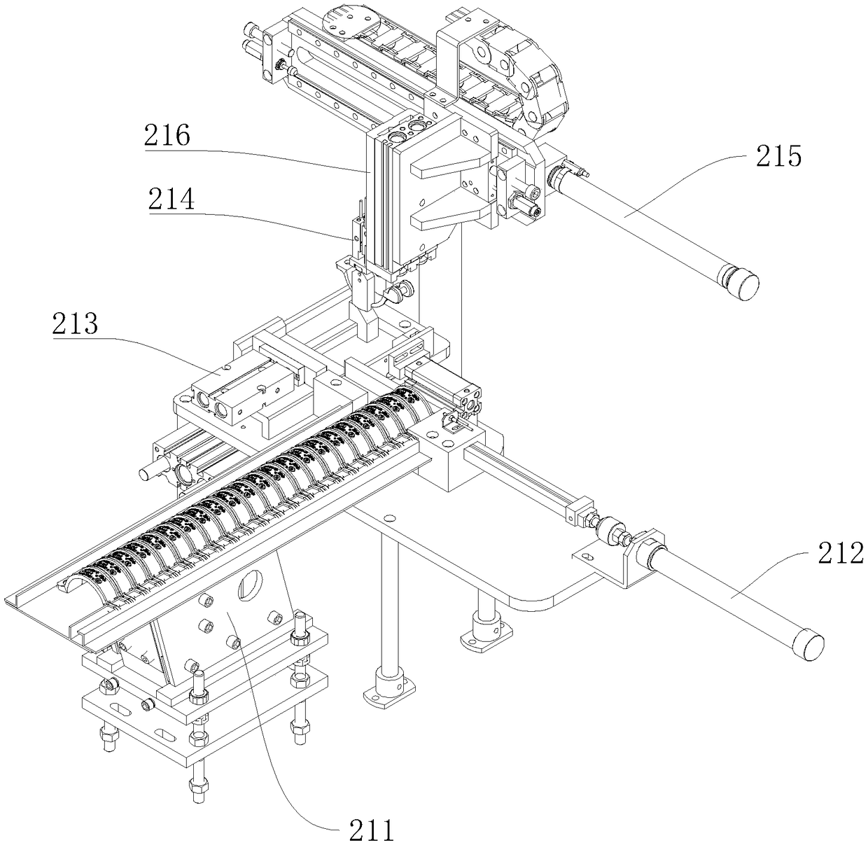
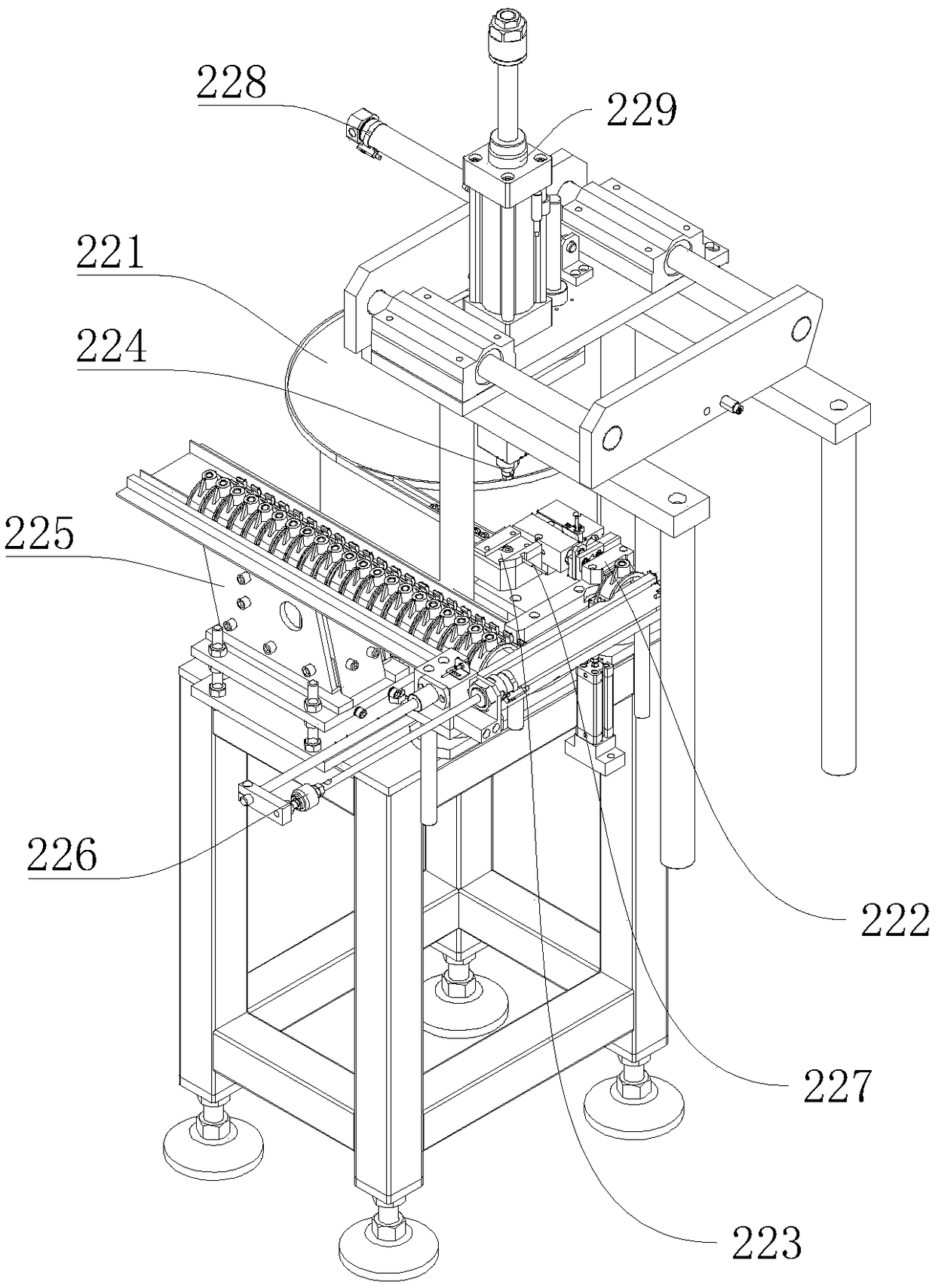
[0028] Such as Figure 1-Figure 6 Shown is a kind of automatic assembly equipment of self-locking type pipe clamp, nut and screw of the present invention, self-locking type pipe clamp such as Figure 7 As shown, it includes a mouthless pipe clamp 11 and a mouthed pipe clamp 12. One end of the mouthless pipe clamp 11 and the mouthed pipe clamp 12 is rotatably connected by a pin shaft, and the other end is detachably connected by a screw 13 and a nut, including: working Table 2, a turntable arranged on the workbench 2, the turntable is used to transport components between the stations, including a turntable body 201, a cam divider 202 arranged at the bottom of the turntable body 201 for driving the turntable body 201 to rotate, and The cam divider 202 is connected to a motor 203 for providing power. Preferably, an eight-degree cam divider 202 is used in this embodiment, and the outer ring of the main body of the turntable 201 is provided with a number of pipe clamps 205 with mou...


PUM


Abstract

The invention discloses automatic assembling equipment of a self-buckling type pipe clamp, a nut and a screw. The automatic assembling equipment comprises a workbench, a rotating disc, an opening-freepipe clamp feeding station, a nut assembling station, a pipe clamp pressing-in station, a pipe clamp assembling station, a screw loading station and a finished product taking-out station, wherein therotating disc is arranged on the workbench, the opening-free pipe clamp feeding station, the nut assembling station, the pipe clamp pressing-in station, the pipe clamp assembling station, the screw loading station and the finished product taking-out station are arranged on the workbench and are arranged around the rotating disc in sequence, an opening-free pipe clamp feeding mechanism, a nut assembling mechanism, a pipe clamp pressing-in mechanism, a pipe clamp assembling mechanism, a screw loading mechanism and a finished product taking-out mechanism are arranged on the opening-free pipe clamp feeding station, the nut assembling station, the pipe clamp pressing-in station, the pipe clamp assembling station, the screw loading station and the finished product taking-out station correspondingly; the outer ring of the rotating disc is provided with a plurality of opening pipe clamp clamps which align with each station, the inner ring of the rotating disc is provided with a plurality of opening-free pipe clamp clamps which align with all the stations correspondingly, and the opening pipe clamps corresponding to each station and the opening pipe clamps abut against each other in an end-to-end mode. According to the automatic assembling equipment, the full-automatic assembly production of the self-buckling type pipe clamp is realized, the production efficiency is improved, the laborinjury caused by manual assembly is reduced, and a large amount of manpower is saved.

Description

technical field [0001] The invention relates to the field of pipe clip assembly, in particular to automatic assembly equipment for self-fastening pipe clips, nuts and screws. Background technique [0002] Nuts and screws are commonly used in the product assembly process. For example, the plastic shell of a toy and the base need to be fixedly connected with nuts and screws. The nuts must be installed in the fixing holes of the base first, and then the shell and the base are connected by screws. . [0003] There are currently two ways to put the nut into the plastic part. One is to inject a certain taper into the nut hole when injecting the plastic part, and then manually knock the nut into the hole for tight fit; the other is to inject the plastic part Finally, use a hot melt tool to melt the nut into the plastic part. However, both of these methods require manual picking and placing of raw materials, and the assembly efficiency is low. [0004] The self-locking pipe clip ...

Claims


Application Information

Patent Timeline
IPC IPC(8): B23P21/00
CPCB23P21/006
Inventor 陈增贵朱梓田王平发沈欧
Owner 湖南湘光机械模具有限公司
Why Eureka
Try Eureka