
Connecting structure of steel structure column and steel structure beam

A technology for steel structure beams and connecting structures, applied in building components, building structures, building insulation materials, etc., can solve unfavorable assembly, delay in construction period, poor structural strength and compressive performance of steel structure columns and steel structure beams, etc. problems, to achieve the effect of improving stability and preventing collapse

Pending Publication Date: 2019-02-12
辰信重工(江苏)有限公司
View PDF0 Cites 5 Cited by
  • Summary
  • Abstract
  • Description
  • Claims
  • Application Information

AI Technical Summary

Problems solved by technology

[0004] The purpose of the present invention is to provide a connection structure between a steel structure column and a steel structure beam to solve the problem that most of the current connection structures proposed in the above background technology require on-site welding, which delays the construction period, is not conducive to assembly, and cannot be properly assembled according to actual needs. The length of the steel structure beam, this kind of connection structure is easy to deform and collapse, and the structural strength and compressive performance of the steel structure column and the steel structure beam are not good.

Method used


Image

  • Connecting structure of steel structure column and steel structure beam
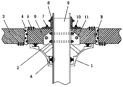
  • Connecting structure of steel structure column and steel structure beam
  • Connecting structure of steel structure column and steel structure beam

Examples


Embodiment Construction

[0021] The following will clearly and completely describe the technical solutions in the embodiments of the present invention with reference to the accompanying drawings in the embodiments of the present invention. Obviously, the described embodiments are only some, not all, embodiments of the present invention. Based on the embodiments of the present invention, all other embodiments obtained by persons of ordinary skill in the art without making creative efforts belong to the protection scope of the present invention.

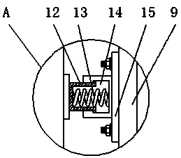
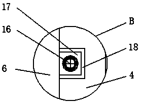
[0022] see Figure 1-4 , an embodiment provided by the present invention: a connection structure between a steel structure column and a steel structure beam, including a second beam body 3, a connecting steel plate 4, a first beam body 6 and a column body 9, and the two sides of the column body 9 The first beam body 6 is installed, and the side of the first beam body 6 close to the column body 9 is fixed with a fixed steel plate 10, the fixed steel plate 10 is...


PUM


Abstract

The invention discloses a connecting structure of a steel structure column and a steel structure beam. The connecting structure comprises a second beam body, a connecting steel plate, first beam bodies and a column body, wherein the first beam bodies are installed on the two sides of the column body, and fixing steel plates are fixed to the sides, close to the column body, of the first beam bodies; the fixing steel plates are connected with the column body through first fixing bolts, and the column body is fixedly connected with the central positions of one sides of the fixing steel plates through fourth fixing bolts; carbon steel reinforced layers are arranged in the side walls of the second beam body, the first beam bodies and the column body, and rubber pressure resistance layers are arranged on the two sides of the carbon steel reinforced layers; and teflon corrosion resistance layers are coated on the outer sides of the second beam body, the first beam bodies and the column body.According to the connecting structure of the steel structure column and the steel structure beam, the column body, the first beam bodies, steel angles, the fixing steel plates, the first fixing bolts,third fixing bolts, and the fourth fixing bolts are installed to facilitate the fixed connection between the first beam bodes and the column body, and the tight connection is not prone to loosing.

Description

technical field [0001] The invention relates to the technical field of a beam-to-column connection structure, in particular to a connection structure between a steel structure column and a steel structure beam. Background technique [0002] Steel structure is a structure mainly composed of steel materials. It is one of the main types of building structures. The structure is mainly composed of steel beams, steel columns and other components made of section steel and steel plates. Because of its light weight and easy construction, Widely used in large factories, venues, super high-rise and other fields. [0003] Most of the existing steel structure columns and steel structure beams are connected by welding, which is easy to cause brittle damage, and requires on-site welding, which affects the construction speed and quality. It is not suitable for fabricated steel structures, and the steel structures of such structures Most of the beams are one-piece structures, which are not ...

Claims


Application Information

Patent Timeline
IPC IPC(8): E04B1/24E04B1/58E04B1/64E04B1/98E04H9/02
CPCE04B1/2403E04B1/642E04H9/021E04H9/024E04B2001/2406
Inventor 史云涛沈丽玉史云娟方俊史云兰
Owner 辰信重工(江苏)有限公司
Learn More