Wiring device and method

A wiring device and wiring pipe technology, applied in the direction of electrical components, etc., can solve the problems of long wiring cycle, high noise, poor construction site environment, etc., and achieve the effects of reducing labor costs, low noise, and shortening wiring time

Pending Publication Date: 2019-02-12
ZHEJIANG YASHA DECORATION
View PDF5 Cites 7 Cited by
  • Summary
  • Abstract
  • Description
  • Claims
  • Application Information

AI Technical Summary

Problems solved by technology

The inventor found in the process of realizing the present invention that the wiring method in the prior art requires on-site construction work, and there are problems such as long wiring cycle, poor construction site environment, and large noise

Method used


Image

  • Wiring device and method
  • Wiring device and method
  • Wiring device and method

Examples


Embodiment 1

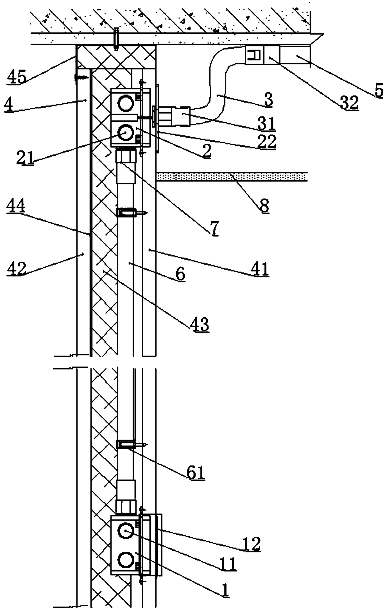
[0022] figure 1 A schematic structural diagram of a wiring device implemented in the present invention is shown, as figure 1 As shown, the wiring device provided by the embodiment of the present invention includes: a pipeline module integrated inside the partition wall 4 .

[0023] The pipeline module includes a first bottom box 1 , a second bottom box 2 , a panel 22 and a wiring pipe 6 for wiring. Wherein, the first bottom box 1 is installed in the first through hole of the partition wall 4 , the second bottom box 2 is installed in the second through hole of the partition wall 4 , and the wiring pipe 6 is installed in the partition wall 4 .

[0024] The first bottom box 1 is provided with a first installation hole 11, the second bottom box 2 is provided with a second installation hole 21, and the first installation hole 11 and the second installation hole 21 pass through the wiring duct 6 connections.

[0025] The panel 22 is covered on the second bottom box 2 , and the pa...

Embodiment 2

[0035] On the basis of the first embodiment above, optionally, as figure 1 As shown, the wiring device further includes: a cup comb 7 through which the wiring pipe 6 is respectively installed in the first installation hole and the second installation hole. By arranging the cup comb 7, damage to the electric wires can be prevented, repeated wiring can be avoided, and wiring efficiency can be improved.

[0036] Such as figure 1 As shown, the cup comb 7 connected to the second bottom box 2, the second bottom box 2, the hose 3, and the top line pipe 5 are all located between the suspended ceiling 8 and the ceiling, and the second bottom box 2 plays a certain transitional role. .

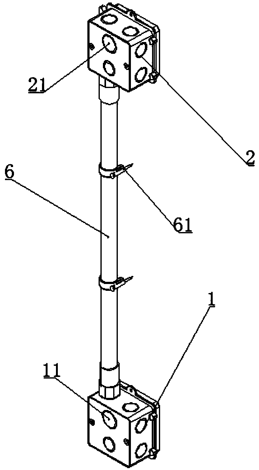
[0037] Further, as image 3 As shown, the wiring device further includes: a saddle card 61 , through which the wiring pipe 6 is fixed on the partition wall 4 , so as to ensure the installation firmness of the wiring pipe 6 .

[0038] Such as figure 1 As shown, the riding cards 61 are fixed on the in...

Embodiment 3

[0050] Based on the wiring device in Embodiment 1 or Embodiment 2, an embodiment of the present invention also provides a wiring method, which includes:

[0051] S110, installing the wiring pipe of the pipeline module in the partition wall;

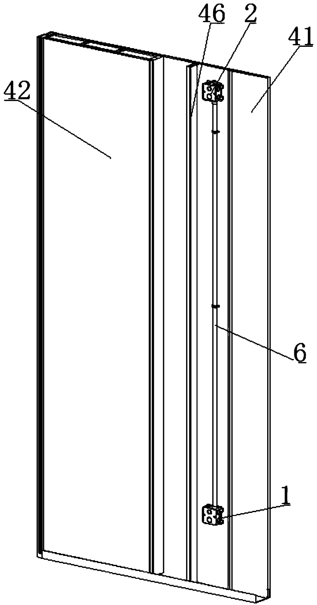
[0052] Such as figure 2 As shown, the pipeline modules are arranged between adjacent keels 45 of the partition wall 4 .

[0053] S120, respectively installing the first bottom box and the second bottom box in the first through hole and the second through hole of the partition wall;

[0054] Such as figure 1 As shown, both the first bottom box 1 and the second bottom box 2 are fixed on the first partition board 41 by fasteners. Fasteners can be screws, bolts and the like.

[0055] S130. Connect the first bottom box and the second bottom box to the wiring pipe respectively, and install the panel cover on the second bottom box.

[0056] Two ends of the wiring pipe 6 are inserted into the first installation hole 11 on the first bottom b...


PUM


Abstract

An embodiment of the invention discloses a wiring device and method. The wiring device comprises a pipeline module integrated in a partition, wherein the pipeline module comprises a first bottom box,a second bottom box, a panel and a wiring tube; the first bottom box is mounted in a first through hole of the partition; the second bottom box is mounted in the second through hole of the partition;the wiring tube is mounted in the partition; a first mounting hole is formed in the first bottom box; a second mounting hole is formed in the second bottom box; the first mounting hole is connected with the second mounting hole through the wiring tube; the panel covers the second bottom box; and the panel is provided with a third mounting hole which is connected with a spool on the top surface. Bythe embodiment of the invention, the wiring time can be greatly shortened, the wiring efficiency is improved, the circumstance that a traditional decoration site is dirty can further be avoided, andthe wiring device is small in noise, low in pollution, and economical and environmentally friendly; and meanwhile, requirements to skills of constructors are low, and thus, the labor cost is greatly reduced.

Description

technical field [0001] The invention relates to the technical field of building decoration, in particular to a wiring device and method. Background technique [0002] In the prior art, the wiring method of the light steel keel partition wall is as follows: first cut a hole in the light steel keel, then pass the wiring pipe through the cut hole for routing, and finally connect with the top surface wire pipe. The inventor found in the process of realizing the present invention that the wiring method in the prior art requires on-site construction work, which has problems such as long wiring period, poor construction site environment, and high noise. Contents of the invention [0003] In view of this, an embodiment of the present invention proposes a wiring device and method to solve the above technical problems. [0004] An embodiment of the present invention provides a wiring device, which includes: a pipeline module integrated in the partition wall, the pipeline module inc...

Claims


Application Information

Patent Timeline
Patent Type & Authority Applications(China)
IPC IPC(8): H02G3/38
CPCH02G3/38
Inventor 丁欣欣丁泽成周东珊王文广王金霞武鹏
Owner ZHEJIANG YASHA DECORATION
Why Eureka
Try Eureka