
Minitype and efficient mechanical plate material automatic bending equipment

An efficient and mechanical technology, applied in the field of mechanical plate automatic bending equipment, can solve the problems of fastening efficiency reduction, device working efficiency reduction, inconvenient removal, etc., achieve good strong adsorption effect and reduce replacement efficiency

Inactive Publication Date: 2019-02-15
黄石盛鼎自动化科技有限公司
View PDF0 Cites 0 Cited by
  • Summary
  • Abstract
  • Description
  • Claims
  • Application Information

AI Technical Summary

Problems solved by technology

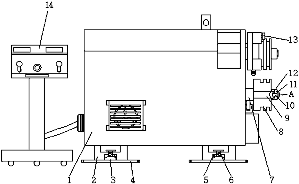
[0003] When the existing small bending machine is in use, the plate to be bent is placed on the roller, and the bending angle is adjusted through the operating table, so that the plate can be bent. According to different sizes and types of plates, the need Replace the corresponding roller to operate it, but the existing rollers all engage the keyway inside it with the flat key on the shaft, so that it is not easy to take out when changing, and at the same time When fixing, use fastening nuts for fastening, so that the fastening efficiency is reduced, thereby reducing the working efficiency of the device. For this reason, we propose a small and efficient mechanical sheet metal automatic bending equipment

Method used


Image

  • Minitype and efficient mechanical plate material automatic bending equipment
  • Minitype and efficient mechanical plate material automatic bending equipment
  • Minitype and efficient mechanical plate material automatic bending equipment

Examples


Embodiment 1

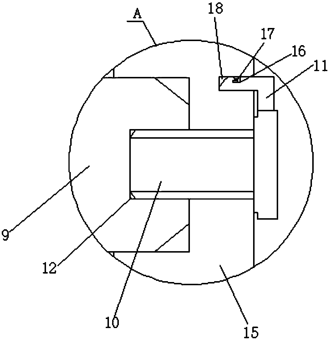
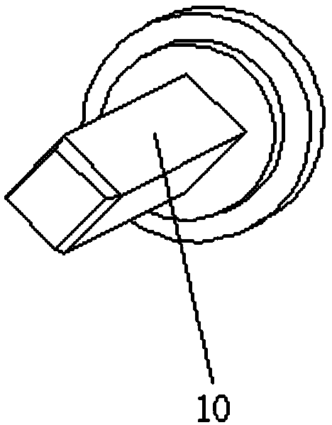
[0024] see Figure 1 to Figure 6 , the present invention provides a technical solution: a small and efficient automatic bending equipment for mechanical plates, including an outer casing 1, a shaft sleeve 7 is arranged on the front surface of the outer casing 1, and a shaft 9 is sleeved inside the shaft sleeve 7, and the shaft 9 The outer wall is sleeved with a rotating roller 8, and the center of the end of the rotating roller 8 is fixed with a fixed block 15. The inner wall of the fixed block 15 and the outer wall of the shaft 9 are attached to each other. The surface of the shaft 9 is provided with a square groove 12, and the surface of the fixed block 15 is provided with a Square hole, the inside of the square hole is provided with a fixed rod 10, through the design of the fixed rod 10, the shape of the fixed rod 10 is square, so that it can be engaged and fixed with the square groove 12 on the end of the shaft rod 9, so that the shaft rod 9 is connected with the rotating ...

Embodiment 2

[0026] see Figure 1 to Figure 7 , the present invention provides a technical solution: a small and efficient automatic bending equipment for mechanical plates, including an outer casing 1, a shaft sleeve 7 is arranged on the front surface of the outer casing 1, and a shaft 9 is sleeved inside the shaft sleeve 7, and the shaft 9 The outer wall is sleeved with a rotating roller 8, and the center of the end of the rotating roller 8 is fixed with a fixed block 15. The inner wall of the fixed block 15 and the outer wall of the shaft 9 are attached to each other. The surface of the shaft 9 is provided with a square groove 12, and the surface of the fixed block 15 is provided with a Square hole, the inside of the square hole is provided with a fixed rod 10, through the design of the fixed rod 10, the shape of the fixed rod 10 is square, so that it can be engaged and fixed with the square groove 12 on the end of the shaft rod 9, so that the shaft rod 9 is connected with the rotating ...


PUM


Abstract

The invention discloses minitype and efficient mechanical plate material automatic bending equipment. The minitype and efficient mechanical plate material automatic bending equipment comprises an outer shell body, the front end face of the outer shell body is provided with a shaft sleeve, the shaft sleeve is internally connected with a shaft rod in a sleeving manner, the outer wall of the shaft rod is connected with a rotating roller in a sleeved manner, the center of the end portion of the rotating roller is fixedly provided with a fixed block, the inner wall of the fixed block is in fit withthe outer wall of the shaft rod, the surface of the shaft rod is provided with a square slot, the surface of the fixed block is provided with a square hole, and the square hole is internally providedwith a fixed rod. According to the minitype and efficient mechanical plate material automatic bending equipment, by means of the design of the fixed rod, the shape of the fixed rod is square, so thatthe fixed rod can be fixed with the square slot in the end portion of the shaft rod in a clamping closing manner to make the shaft rod be connected into a whole with the rotating roller and make theshaft rod drive the rotating roller to rotate, when the rotating roller needs to be replaced, the rotating roller can be disassembled by pulling the rotating roller out directly, and the situation that a flat key and a key slot further need to be aligned to perform fixing then in traditional replacement of the rotating roller, and because the flat key and the key slot are matched too tightly, therotating roller is inconvenient to disassemble in subsequent replacement of the rotating roller is avoided.

Description

technical field [0001] The invention belongs to the technical field of automatic bending equipment, and in particular relates to a small and efficient automatic bending equipment for mechanical plates. Background technique [0002] Small bending machines are mainly used for bending plates used in electric power construction, boilers, and bridge lights. They have the advantages of multiple functions, reasonable structure, and simple operation. Compared with large bending equipment, they are cheap and easy to use. They are popular in China. The market occupies a dominant product position. [0003] When the existing small bending machine is in use, the plate to be bent is placed on the roller, and the bending angle is adjusted through the operating table, so that the plate can be bent. According to different sizes and types of plates, the need Replace the corresponding roller to operate it, but the existing rollers have their internal keyways and flat keys on the shaft engaged...

Claims


Application Information

Patent Timeline
Patent Type & Authority Applications(China)
IPC IPC(8): B21D5/08
CPCB21D5/08
Inventor 李勇
Owner 黄石盛鼎自动化科技有限公司
Learn More