Reversible sanitary appliance production line
A production line, flip-type technology, applied in the direction of die-casting molds, manufacturing tools, unloading devices, etc., can solve the problem of high air bubble rate in toilet products, achieve the effect of reducing air bubble rate, improving quality, and convenient entry and exit of molds
- Summary
- Abstract
- Description
- Claims
- Application Information
AI Technical Summary
Problems solved by technology
Method used
Image
Examples
Embodiment 1
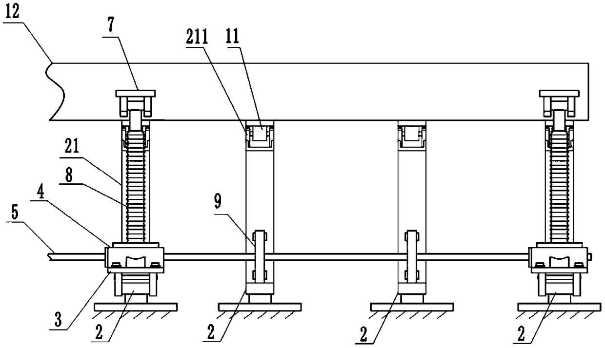
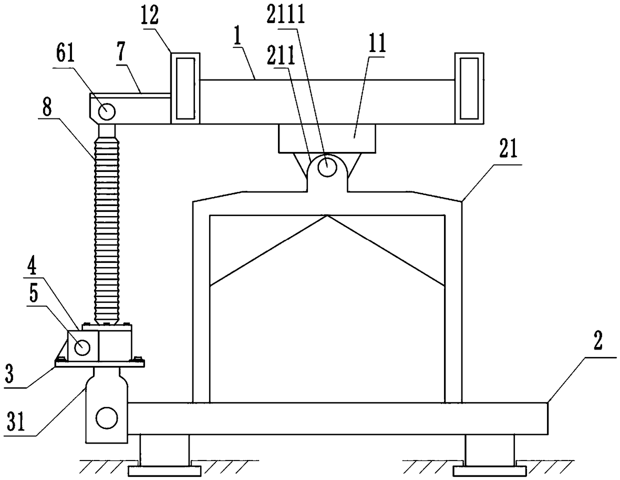
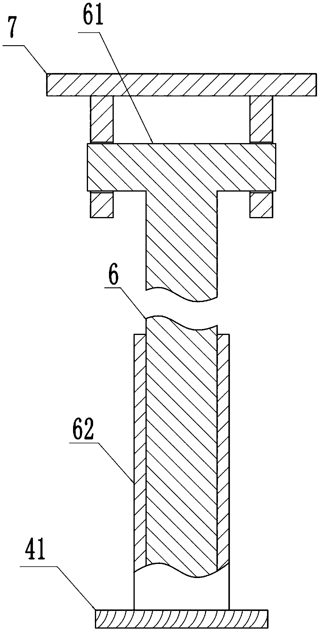
[0035] Basic as attached Figure 1~3 Shown: a reversible sanitary ware production line, including a processing table 1 and a mold base in the prior art, and the processing table 1 is located above the mold base; the improvement is that, as figure 1 The bottom of the shown processing table 1 is horizontally fixed with a row of rotating ears 11; the formwork includes a base 2 and a support frame 21, and the number of rotating ears 11, base 2, and support frames 21 is the same; each support frame 21 is connected to a base 2 respectively. fixed; the top of the support frame 21 is fixed as figure 2 As shown in the connecting ears 211, each connecting ear 211 is rotatably connected with a rotating shaft 2111, and each rotating shaft 2111 is respectively fixed with a rotating ear 11, so as to facilitate figure 2 The processing table 1 in the middle can rotate left and right along with the rotating shaft 2111. Such as figure 2 As shown, the left and right sides of the processing...
Embodiment 2
[0043] The difference between this embodiment and Embodiment 1 is that the rotation of the processing table is driven by a rack and pinion, specifically: the transmission member 41 is a rack; the telescopic part is a transmission shaft, and the rack is fixed on the side wall of the transmission shaft. The upper end of the upper end is fixed with movable shaft 61, and then realizes the hinge of transmission shaft and processing table left end slide rail 12. The part of the drive shaft 5 extending into the housing 4 is fixed with a gear for cooperating with the rack; when the drive shaft 5 rotates, the gear rotates, and the gear can move the rack upwards or downwards, thereby making the transmission shaft move up and down, realizing The rotation of the processing table 1.
PUM
 Abstract
Description
Claims
Application Information
 - R&D
- Intellectual Property
- Life Sciences
- Materials
- Tech Scout
- Unparalleled Data Quality
- Higher Quality Content
- 60% Fewer Hallucinations
Browse by: Latest US Patents, China's latest patents, Technical Efficacy Thesaurus, Application Domain, Technology Topic, Popular Technical Reports.
© 2025 PatSnap. All rights reserved.Legal|Privacy policy|Modern Slavery Act Transparency Statement|Sitemap|About US| Contact US: help@patsnap.com


