
Metal plate winding device

A technology of winding device and metal plate, which is applied in the direction of winding strips, transportation and packaging, thin material processing, etc., can solve the problems of untimely winding, metal plate pile up, damage to the winding device, etc., and achieve the effect of improving the service life

Inactive Publication Date: 2019-02-15
鹤山市源创电机有限公司
View PDF0 Cites 0 Cited by
  • Summary
  • Abstract
  • Description
  • Claims
  • Application Information

AI Technical Summary

Problems solved by technology

When the current metal plate winding device is wound, the winding is often not timely, which will cause the metal plate to pile up, and even damage the winding device itself.

Method used


Image

  • Metal plate winding device

Examples


Embodiment Construction

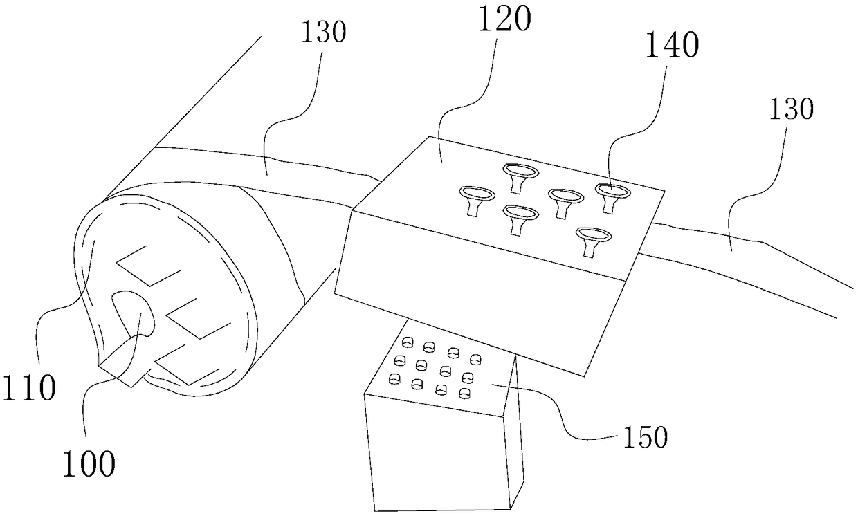
[0014] The metal plate 130 is needed to produce the steel structure, and the formed metal plate 130 usually needs to be wound to facilitate transportation and storage. When the current winding device for metal plate 130 is wound, it often occurs that the winding is not timely, which will cause the metal plate 130 to pile up, and even damage the winding device itself in serious cases. Devices, such as guide rails, rollers, etc., are sent to the front side of the winding device, and finally the winding device is wound. It can be seen that if the speed is too fast on the front side, the following winding device may not be able to respond to the winding, and the above problems will also occur. , in the same way, if the speed is too slow on the front side, the winding device may waste winding time and resources, such as electricity, labor costs, etc., which is not worth the candle.

[0015] Based on this, refer to figure 1 , the embodiment of the present invention provides a metal...


PUM


Abstract

The invention discloses a metal plate winding device. The metal plate winding device comprises a winding device for winding metal plates, and an adjusting device for adjusting the winding speed of themetal plates; and the adjusting device is arranged on the front side of the winding device. Compared with the prior art, the metal plate winding device can adjust the winding speed of the metal plates to prevent the unmatched condition in actual winding, and facilitates prolonging of the service life.

Description

technical field [0001] The invention relates to the field of metal plate processing, in particular to a metal plate winding device. Background technique [0002] The production of steel structures requires metal plates. In order to facilitate transportation, storage, etc., it is usually necessary to wind the formed metal plates. When the current metal sheet winding device is winding, the winding often fails to be timely, which in turn causes the metal sheets to pile up, and seriously even damages the winding device itself. Contents of the invention [0003] In order to solve the above problems, the purpose of the embodiment of the present invention is to provide a metal plate winding device, which can adjust the metal plate winding speed, prevent the winding from being untimely, and help to improve the service life of the winding device. [0004] In order to make up for the deficiencies in the prior art, the technical solution adopted in the embodiment of the present inve...

Claims


Application Information

Patent Timeline
Patent Type & Authority Applications(China)
IPC IPC(8): B65H18/10B65H23/188
CPCB65H18/10B65H23/188B65H2701/11332B65H2701/173
Inventor 麦启源
Owner 鹤山市源创电机有限公司
Learn More