
Creel for textile

A creel and base technology, applied in the field of textile winding, can solve the problems of inability to adjust the speed of different yarns, yarn damage, poor balance performance, etc., and achieve the effects of convenient and fast installation and replacement, fast installation and simple structure

Inactive Publication Date: 2018-08-24
XIANGSHUI YONGTAI TEXTILE GARMENT CO LTD
View PDF0 Cites 0 Cited by
  • Summary
  • Abstract
  • Description
  • Claims
  • Application Information

AI Technical Summary

Problems solved by technology

In the prior art, in the weaving process, the yarn creel is generally used to place the yarn bobbin in the knitting field. The creel includes a support rod and a plurality of bobbin rods. On the support rod, spinning needs to be wound on the bobbin, and the yarn is transported to the conveying device of the knitting machine after passing through the bobbin, for the next step of processing or for sale as a semi-finished product. Therefore, there must be a lot of creels in textile production engineering. Now Some creels have simple structures and poor balance performance, and the speed cannot be adjusted according to different yarns, and the yarns will generate static electricity during the winding process, causing damage to the yarns

Method used


Image

  • Creel for textile
  • Creel for textile

Examples


Embodiment Construction

[0018] The following will clearly and completely describe the technical solutions in the embodiments of the present invention with reference to the accompanying drawings in the embodiments of the present invention. Obviously, the described embodiments are only some, not all, embodiments of the present invention.

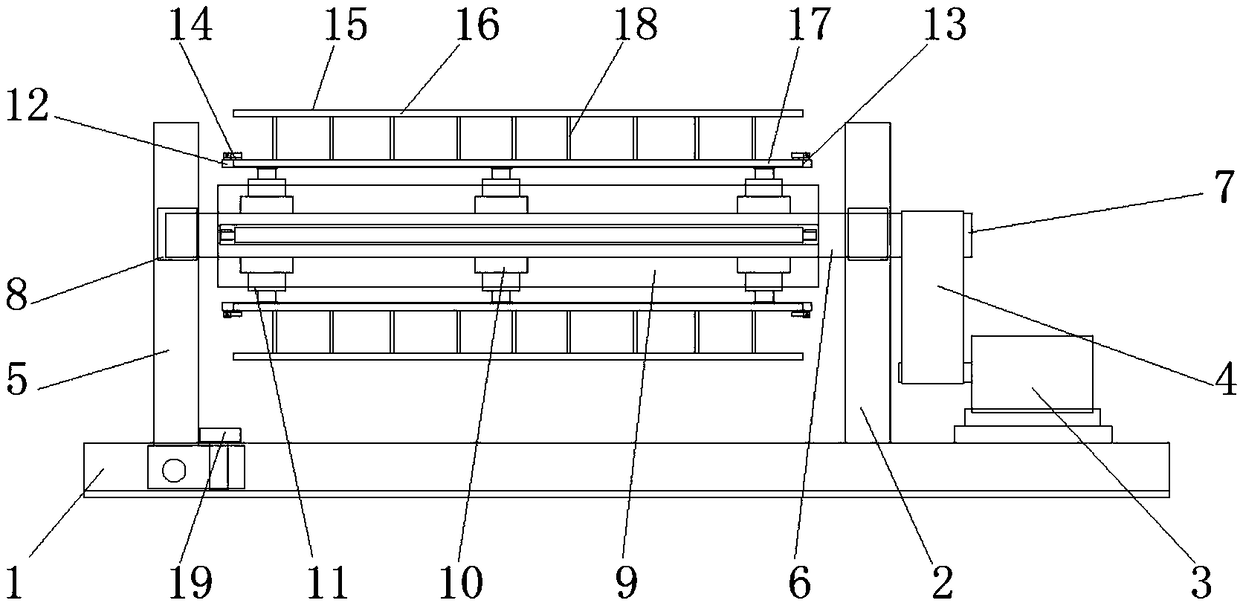
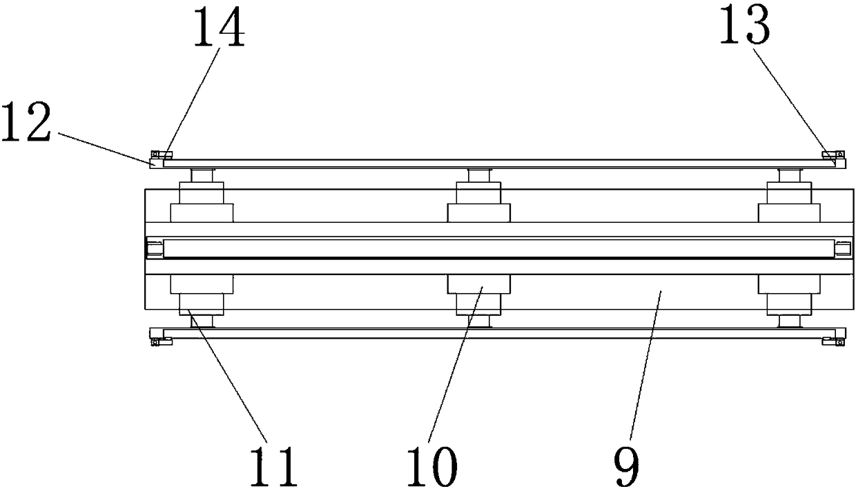
[0019] refer to Figure 1-2 , a creel for textiles, comprising a base 1, a first support 2 is provided on one side of the top of the base 1, a motor 3 is provided on the top of the base 2 on one side of the first support 2, the The output shaft sleeve of the motor 3 is provided with a belt 4, and the top of the base 1 is provided with a second support 5 that is movably connected on the other side of the first support 2. Between the first support 2 and the second support 5 Wheel rollers 6 are arranged between them, and rotating shafts 7 are arranged at both ends of the wheel rollers 6. Bearing blocks 8 matching the rotating shafts 7 are arranged in the first support 2...


PUM


Abstract

The invention discloses a creel for a textile. The creel for the textile comprises a base. A first bracket is arranged on one side of the top of the base. A motor is arranged at the top of the base and located at one side of the first bracket. An output shaft of the motor is sleeved with a belt. A second bracket which is movably connected is arranged at the top of the base and located at the otherside of the first bracket. A wheel roller is arranged between the first bracket and the second bracket. Rotating shafts are arranged at both ends of the wheel roller. Bearing seats are arranged in the first bracket and the second bracket. The wheel roller is sleeved with a connecting cylinder. A plurality of sets of hydraulic cylinders are arranged on the inner wall of the connecting cylinder. Through holes which are matched with the hydraulic cylinders are formed in the outer wall of the connecting cylinder. A plurality of connecting plates are arranged on the outer side of the connecting cylinder. Installation grooves are formed in the connecting plates. Fixed clamps are arranged symmetrically on both sides of the connecting plates. Yarn winding frames are arranged on the outer sides ofthe connecting plates in a matched mode. The yarn winding frames comprise yarn winding plates and installation plates, and a plurality of connecting rods are arranged between the yarn winding platesand the installation plates. According to the creel for the textile, the structure is simple, the installation and replacement are convenient and rapid, the yarn winding speed can be adjusted, and convenience and practicality are achieved.

Description

technical field [0001] The invention relates to the technical field of textile winding, in particular to a spinning frame for textile. Background technique [0002] The original meaning of textile is taken from the general term of spinning and weaving, but with the continuous development and improvement of the textile knowledge system and subject system, especially after the emergence of non-woven textile materials and three-dimensional composite weaving technologies, the current textile is not only a traditional Hand spinning and weaving also include clothing, industrial and decorative textiles produced by non-woven technology, modern three-dimensional weaving technology, and modern electrostatic nano-netting technology. Therefore, modern textile refers to a kind of fiber or fiber collection. Solid multi-scale structure processing technology. In the prior art, in the weaving process, the yarn creel is generally used to place the yarn bobbin in the knitting field. The creel...

Claims


Application Information

Patent Timeline
IPC IPC(8): B65H54/44B65H54/553B65H75/24
CPCB65H54/44B65H54/553B65H75/242B65H2701/31
Inventor 夏平
Owner XIANGSHUI YONGTAI TEXTILE GARMENT CO LTD
Learn More