
Lock sealing structure for yarn dyeing

A sealing structure, yarn dyeing technology, applied in textile and papermaking, textile processing machine accessories, textile material processing and other directions, can solve problems such as insufficient dyeing liquid pressure, yarn roll flushing, dyeing liquid leakage, etc., to avoid The phenomenon of dyeing flowers and avoiding the effect of flushing

Inactive Publication Date: 2019-02-15
无锡得金印染机械厂
View PDF5 Cites 2 Cited by
  • Summary
  • Abstract
  • Description
  • Claims
  • Application Information

AI Technical Summary

Problems solved by technology

Generally, the lock cover part is in contact with the yarn part, the yarn bobbin sealing part is in contact with the dyeing tube, and the yarn column tooth bar is in contact with the intermediate sealing ring through the lock core tube. This part can be sealed without leakage, but the lock spring There is a gap between the core tube at the bottom and the sealing seat. The core tube needs to move up and down during long-term use, and the seal cannot be achieved, resulting in leakage of the dyeing solution, resulting in insufficient pressure of the dyeing solution, not only causing dyeing and layering of the yarn, It also causes flushing of the uppermost yarn reel that is in contact with the lock, so yarn quality will be poorer in dyeing machines using such locks

Method used


Image

  • Lock sealing structure for yarn dyeing
  • Lock sealing structure for yarn dyeing
  • Lock sealing structure for yarn dyeing

Examples


Embodiment

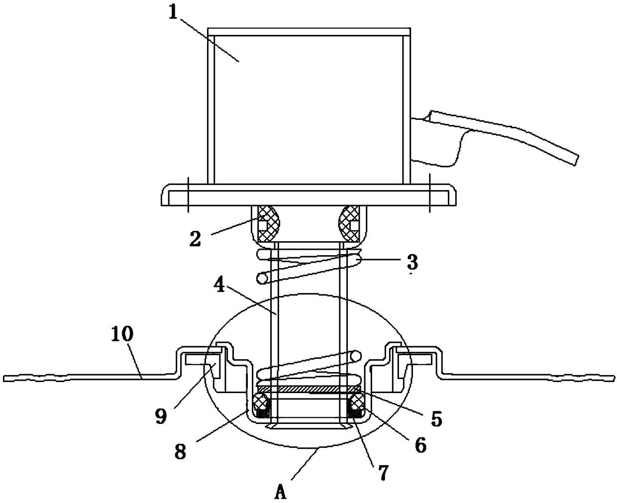
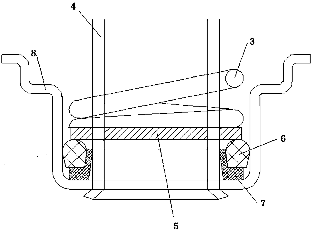
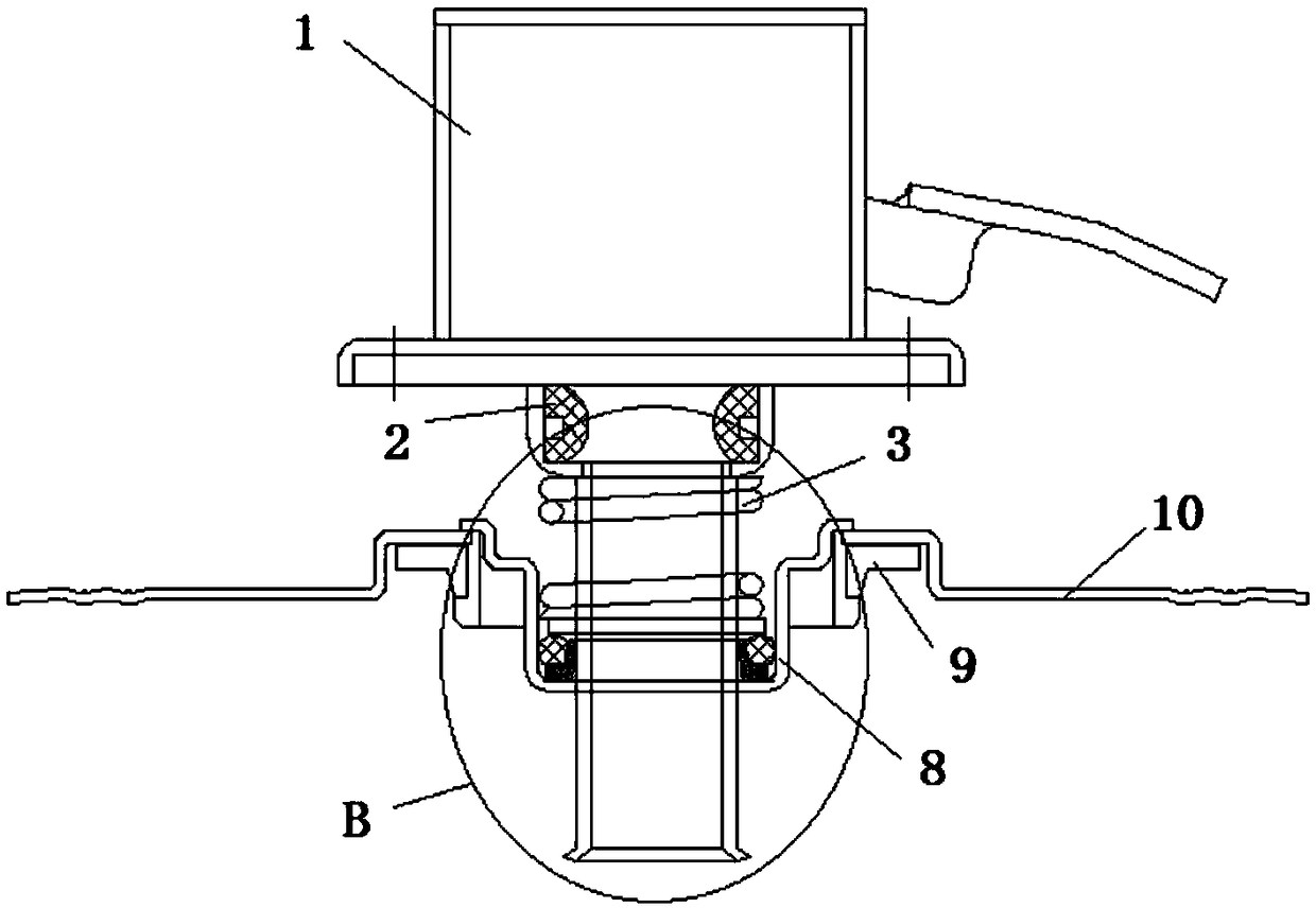
[0027] Such as Figure 1 to Figure 4 As shown, a lock head sealing structure for yarn dyeing includes a locking part 1, an intermediate sealing ring 2 is installed at the lower end of the locking part 1, and a core tube 4 is provided at the lower end of the intermediate sealing ring 2, and the outer sleeve of the core tube 4 is A spring 3 is provided, a sealing seat 8 is provided on the outer side of the core tube 4, and a bobbin sealing part 9 is provided on the periphery of the sealing seat 8, and the bobbin sealing part 9 is connected with a cover sheet 10; the lower end of the spring 3 is provided with a gasket 5;

[0028] An annular elastic pad 2 7 is arranged between the core tube 4 and the sealing seat 8, and an annular groove 701 is formed on the outer upper part of the elastic pad 2 7; an annular elastic pad 1 6 is arranged in the groove 701;

[0029] Such as Figure 5 As shown, the bottom of the groove 701 is a plane, the bottom of the elastic pad 6 is a plane match...


PUM


Abstract

The invention discloses a lock sealing structure for yarn dyeing. The structure comprises a locking portion, an intermediate sealing ring is arranged at the lower end of the locking portion, a core tube is arranged at the lower end of the intermediate sealing ring, and a spring is arranged on the outside of the core tube; the lower end of the spring is provided with a gasket; a second annular elastic pad is disposed between the core tube and a sealing seat, and an annular groove is formed in the outer upper portion of the second elastic pad; an annular first elastic pad is arranged in the groove; the bottom of the groove is a plane, the bottom of the first elastic pad is a plane matching the groove, and the bottom of the first elastic pad is embedded in the groove; the natural height of the first elastic pad is higher than the height of the groove; the upper end of the first elastic pad abuts against the lower side surface of the gasket. The structure adds two sealing structures of thefirst elastic pad and the second elastic pad at the bottom of the spring, achieves the effect of completely sealing a lock head, does not cause leakage problem during long-term use, avoids the unevenly dyeing phenomenon of a dyed yarn, and avoids yarn roughing.

Description

technical field [0001] The invention relates to the field of yarn dyeing equipment, in particular to a lock head sealing structure for yarn dyeing. Background technique [0002] When dyeing the yarn, it is necessary to wind the yarn evenly on the dyeing bobbins with densely packed holes, then set the dyed bobbins on the bobbins one by one, and use the lock head and the teeth on the bobbins to The strip locks the dyeing tubes on the same yarn column, and a dyeing unit is formed by the yarn column base, multiple dyeing tubes and lock heads. Finally, install multiple dyeing units on the creel, the dye solution is sprayed from the bottom of the creel, and the dye solution is sprayed from the inner wall of the dyeing tube. After the dyeing solution passes through the small hole, it enters the yarn on the dyeing tube, thereby achieving yarn alignment. The dyeing of the thread. Generally, the lock cover part is in contact with the yarn part, the yarn bobbin sealing part is in con...

Claims


Application Information

Patent Timeline
Patent Type & Authority Applications(China)
IPC IPC(8): D06B23/04
CPCD06B23/047
Inventor 胡卿
Owner 无锡得金印染机械厂
Learn More