Rapid extracting device for gas under well shaft

A fast and gas-fired technology, applied in the direction of gas discharge, safety devices, mining equipment, etc., can solve the problem of uneven gas concentration drop, achieve the effect of rapid gas concentration drop and expand the suction range

Pending Publication Date: 2019-02-15
NORTH CHINA INST OF SCI & TECH
View PDF0 Cites 0 Cited by
  • Summary
  • Abstract
  • Description
  • Claims
  • Application Information

AI Technical Summary

Problems solved by technology

[0004] The purpose of the present invention is to provide an underground gas rapid extraction device t

Method used


Image

  • Rapid extracting device for gas under well shaft
  • Rapid extracting device for gas under well shaft
  • Rapid extracting device for gas under well shaft

Examples


Example Embodiment

[0021] The technical solutions of the present invention will be clearly and completely described below in conjunction with the accompanying drawings. Obviously, the described embodiments are part of the embodiments of the present invention, rather than all of them. Based on the embodiments of the present invention, all other embodiments obtained by those of ordinary skill in the art without creative work shall fall within the protection scope of the present invention.

[0022] In the description of the present invention, it should be noted that the terms "center", "upper", "lower", "left", "right", "vertical", "horizontal", "inner", "outer", etc. The indicated orientation or positional relationship is based on the orientation or positional relationship shown in the drawings, and is only for the convenience of describing the present invention and simplifying the description, rather than indicating or implying that the pointed device or element must have a specific orientation or a ...


PUM


Abstract

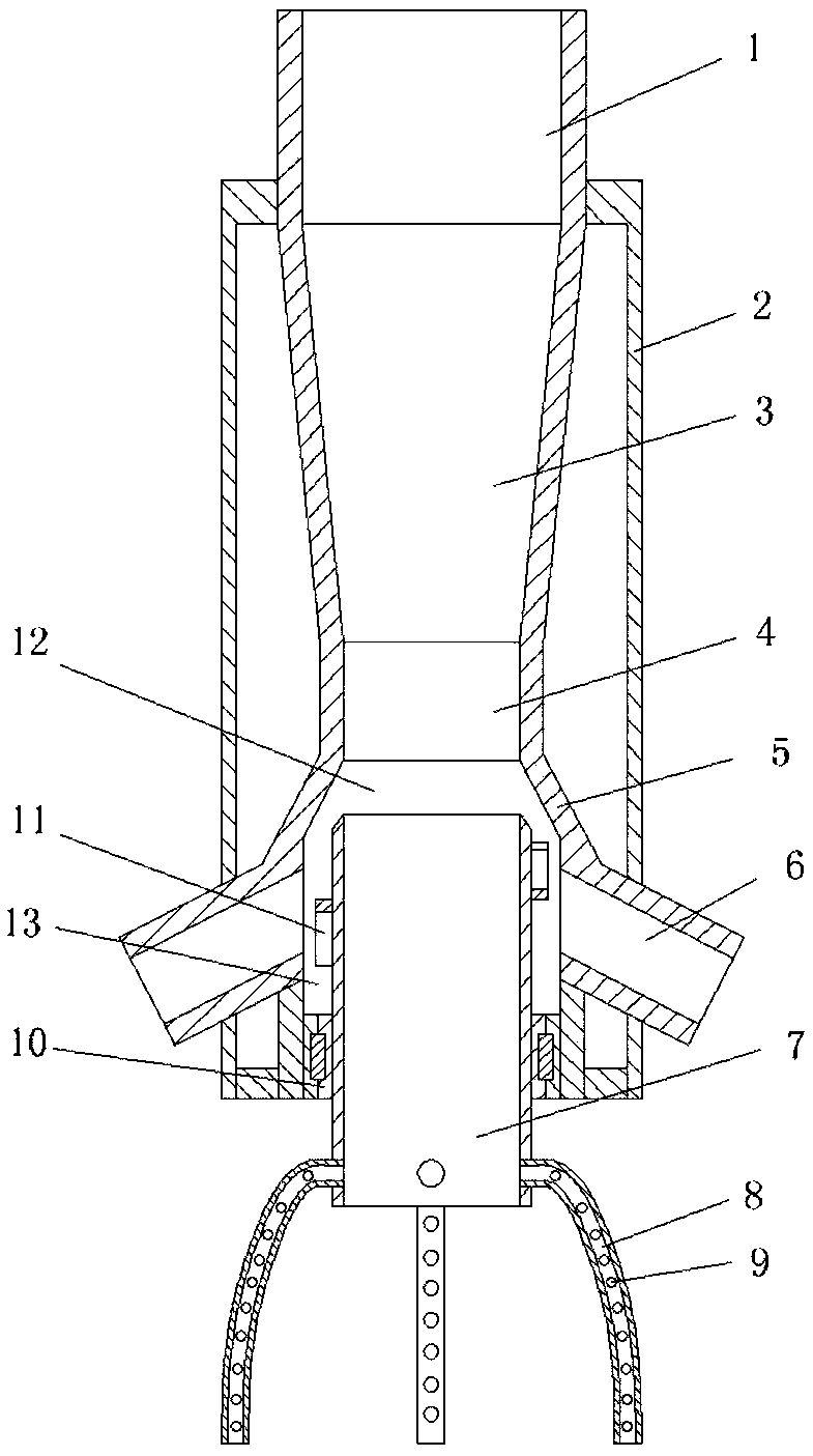
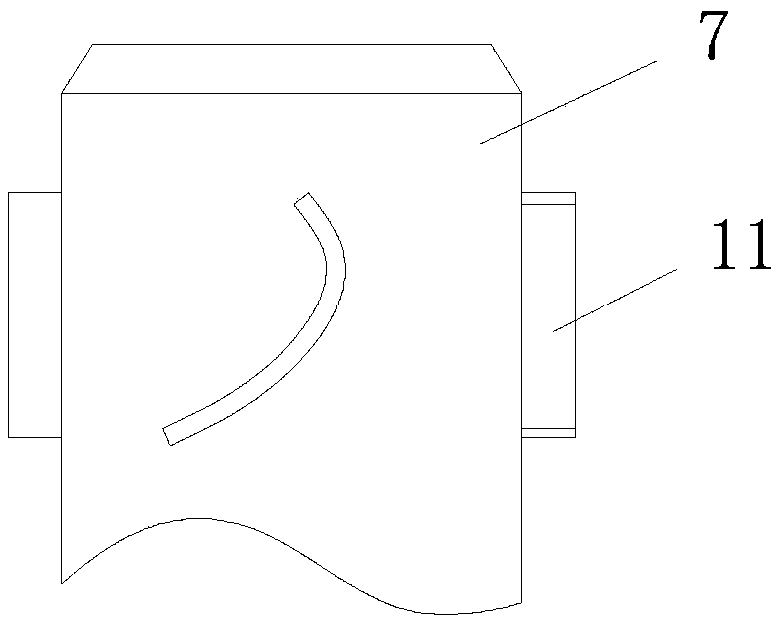
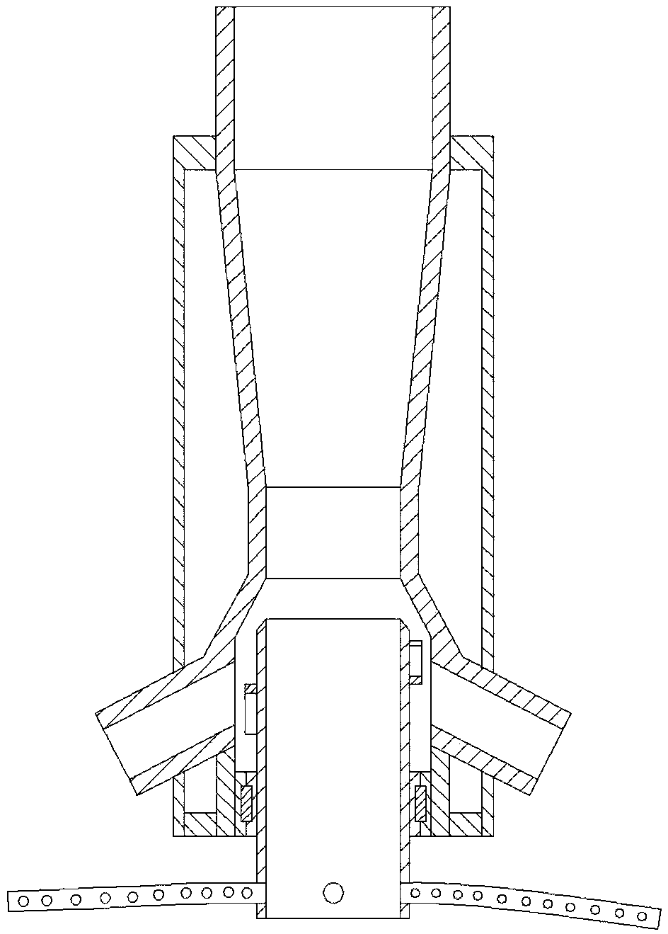
The invention provides a rapid extracting device for gas under a well shaft. The rapid extracting device comprises a gas jet flow pump body, the gas jet flow pump body comprises a diffusing pipe groupon the upper part, a rotary suction pipe and gas flow spraying pipes on the lower part, a flow leading cavity which is connected with the diffusing pipe group is arranged on the lower part of the diffusing pipe group, and the rotary suction pipe is arranged on the flow leading cavity through sealing bearings and is coaxial with the diffusing pipe group; and the gas flow spraying pipes are arranged on the side walls of the flow leading cavity, intersection angles of the spraying directions of gas flow of the gas flow spraying pipes and the axes of the diffusing pipe group are obtuse angles, sailboards are arranged at the area, where spraying gas flow applies pressure, of the side walls, the spraying gas flow acts on the sailboards to enable the rotary suction pipe to rotate around the axisof the rotary suction pipe, and a gas suction hose is arranged at the position, near the lower end, of the rotary suction pipe. According to the rapid extracting device for the gas under the well shaft, while using a flow spraying theory to extract the gas under the well shaft, rotation of the rotary suction pipe is realized, the gas suction hose is driven to swing under the well shaft, a gas suction range is expanded, and air under the well shaft is disturbed to enable a rapid decline of dense of the gas in larger range space.

Description

technical field [0001] The invention relates to the technical field of coal mining, in particular to an underground gas quick extraction device. Background technique [0002] At present, a mine gas extraction device must be used in the mine to ensure that the gas concentration in the mine is within a safe range. The existing mine gas extraction device includes an electric control box, a gas meter and Discharge mechanism. When the gas concentration in the mine reaches or exceeds the allowable value, the electric control box starts the gas extraction mechanism. However, the existing mine gas extraction device extracts gas at a slow rate. When extracting gas, it is placed in the mine An extraction port deep in the mine draws the gas away, so the gas concentration far from the extraction port cannot drop rapidly, and the safety factor of the mine is still low. [0003] The information disclosed in the background technology section is only intended to deepen the understanding of...

Claims


Application Information

Patent Timeline
IPC IPC(8): E21F7/00F04F5/16
CPCE21F7/00F04F5/16
Inventor 程志恒张科学王公达冯吉成陈亮赵晶吴波孙健东李正胜王维华杨正凯桑聪姜黎明
Owner NORTH CHINA INST OF SCI & TECH
Why Eureka
Try Eureka