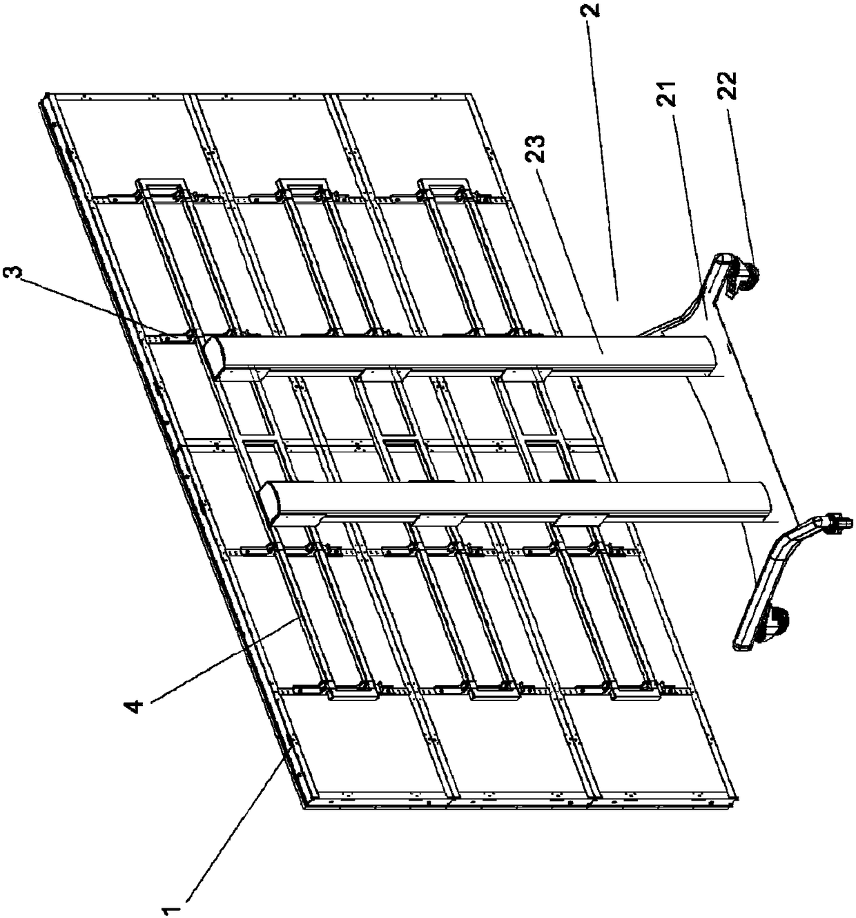
Joint screen supporting structure

A support structure and splicing screen technology, which is applied in the field of display screens, can solve problems such as skew or corners that cannot be aligned, and achieve the effect of improving integrity, avoiding skew, and smoothing the splicing screen

Pending Publication Date: 2019-02-15
XIAMEN YINQIAO OPTOELECTRONICS TECH CO LTD
View PDF11 Cites 4 Cited by
  • Summary
  • Abstract
  • Description
  • Claims
  • Application Information

AI Technical Summary

Problems solved by technology

[0003] The purpose of the present invention is to overcome the above-mentioned defects or problems in the background technology, and provide a splicing screen support structure to solve the situation that the existing splicing screens are skewed or the corners cannot be aligned after splicing

Method used


Image

  • Joint screen supporting structure
  • Joint screen supporting structure
  • Joint screen supporting structure

Examples


Embodiment Construction

[0030] The following will clearly and completely describe the technical solutions in the embodiments of the present invention with reference to the drawings in the embodiments of the present invention. Obviously, the described embodiments are preferred embodiments of the invention and should not be seen as excluding other embodiments. Based on the embodiments of the present invention, all other embodiments obtained by persons of ordinary skill in the art without creative efforts fall within the protection scope of the present invention.

[0031] In the claims, description and above-mentioned drawings of the present invention, unless otherwise clearly defined, the terms "first", "second" or "third" are used to distinguish different objects, not for Describe a specific order.

[0032] In the claims, specification and above-mentioned drawings of the present invention, unless otherwise clearly defined, for orientation words, such as using the terms "center", "transverse", "longit...


PUM


Abstract

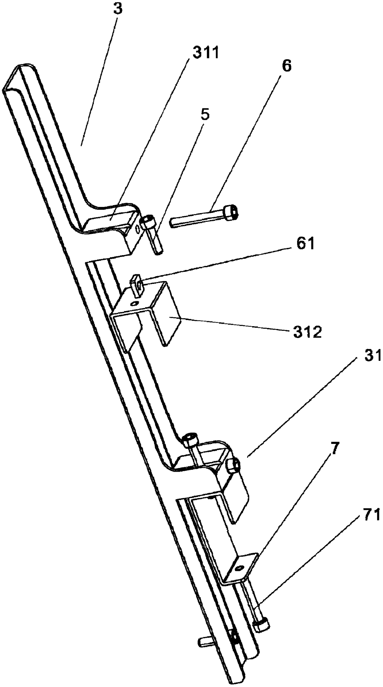
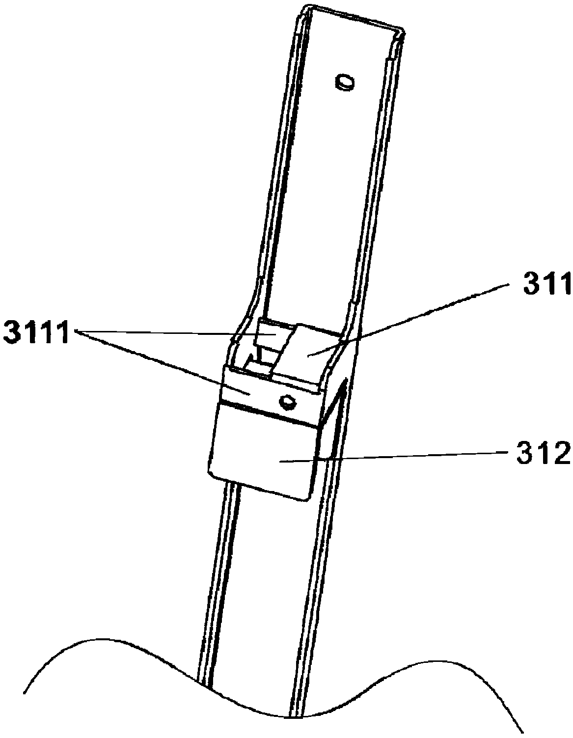
The invention discloses a joint screen supporting structure. The joint screen supporting structure is used for supporting a joint screen formed by splicing a plurality of screen modules and comprisesa base, a hanging frame, a support and first screw rods; the hanging frame is fixedly connected with the back portions of the screen modules and provided with hook assemblies; the support is fixedly connected with the base and comprises horizontally-extending cross rods; the screen modules are hung on the cross rods of the support through the hook assemblies; and the first screw rods penetrate through and are in screwed connection with the hook assemblies in the vertical direction. By the adoption of the joint screen supporting structure, the height positions of the screen modules can be adjusted through the first screw rods, so that gaps between the screen modules are avoided, and the vision impression is improved.

Description

technical field [0001] The invention relates to the technical field of display screens, in particular to a splicing screen support structure. Background technique [0002] Existing LED installation methods usually require professionals to install individual LED screens in order to form a large-area screen in the manufactured box. The installation process is complicated, the process takes a long time, and the labor cost is high. The LED screen is preset as a modular display product, and then the modular product is assembled and spliced ​​to reduce the installation cost of the LED screen. However, during the splicing process of multiple modular products, due to the size of the preset modular product The slight difference will cause the spliced ​​LED screen to be skewed or the corners cannot be aligned, which greatly reduces the visual perception. Contents of the invention [0003] The purpose of the present invention is to overcome the above-mentioned defects or problems in...

Claims


Application Information

Patent Timeline
Patent Type & Authority Applications(China)
IPC IPC(8): F16M11/04G09F9/00
CPCG09F9/00F16M11/04G09F9/33G09F9/3026F16M11/42F16M11/22F16M11/24F16M13/02F16M11/045F16M11/046F16M11/048F16M11/08F16M11/10F16M11/105G09F9/3023
Inventor 饶晦晗李其祥
Owner XIAMEN YINQIAO OPTOELECTRONICS TECH CO LTD
Why Eureka
Try Eureka