An ice thickness monitoring device and method based on the principle of water body liquid-solid phase change volume change

A monitoring device and variable volume technology, applied in mechanical thickness measurement and other directions, can solve problems such as low efficiency, large error, and observation cost constraints, and achieve simple and convenient installation and disassembly operations, avoiding waste of manpower and resources, and stable and reliable operation. Effect

Active Publication Date: 2020-05-26
NORTHEAST AGRICULTURAL UNIVERSITY
View PDF6 Cites 2 Cited by
  • Summary
  • Abstract
  • Description
  • Claims
  • Application Information

AI Technical Summary

Problems solved by technology

This method needs to drill holes on the ice surface and measure with a straightedge. It is not suitable to observe the intersection position of the bottom of the ice layer, and the error is large. In addition, its low efficiency cannot meet the needs of continuous detection of fixed-point ice thickness.
[0004] At present, a variety of automatic ice thickness observation technologies have been developed at home and abroad. The application of mooring sonar and ultrasonic detection technology has realized the automatic monitoring of fixed-point ice thickness changes, but its measurement accuracy is easily affected by the monitoring environment and the physical properties of ice water. In addition, , sonar and ultrasonic detection technology have a large one-time investment, and the deployment of large-scale ice thickness observation devices is restricted by observation funds, which limits the development of ice engineering to refinement

Method used


Image

  • An ice thickness monitoring device and method based on the principle of water body liquid-solid phase change volume change
  • An ice thickness monitoring device and method based on the principle of water body liquid-solid phase change volume change
  • An ice thickness monitoring device and method based on the principle of water body liquid-solid phase change volume change

Examples


Embodiment Construction

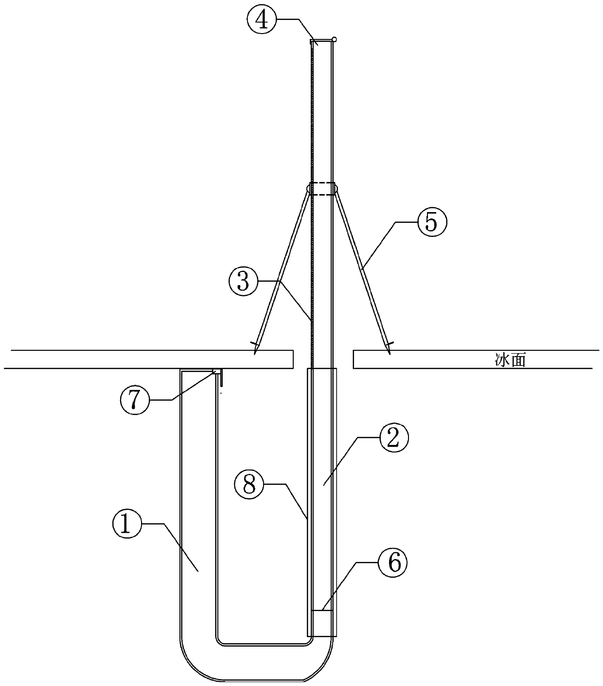
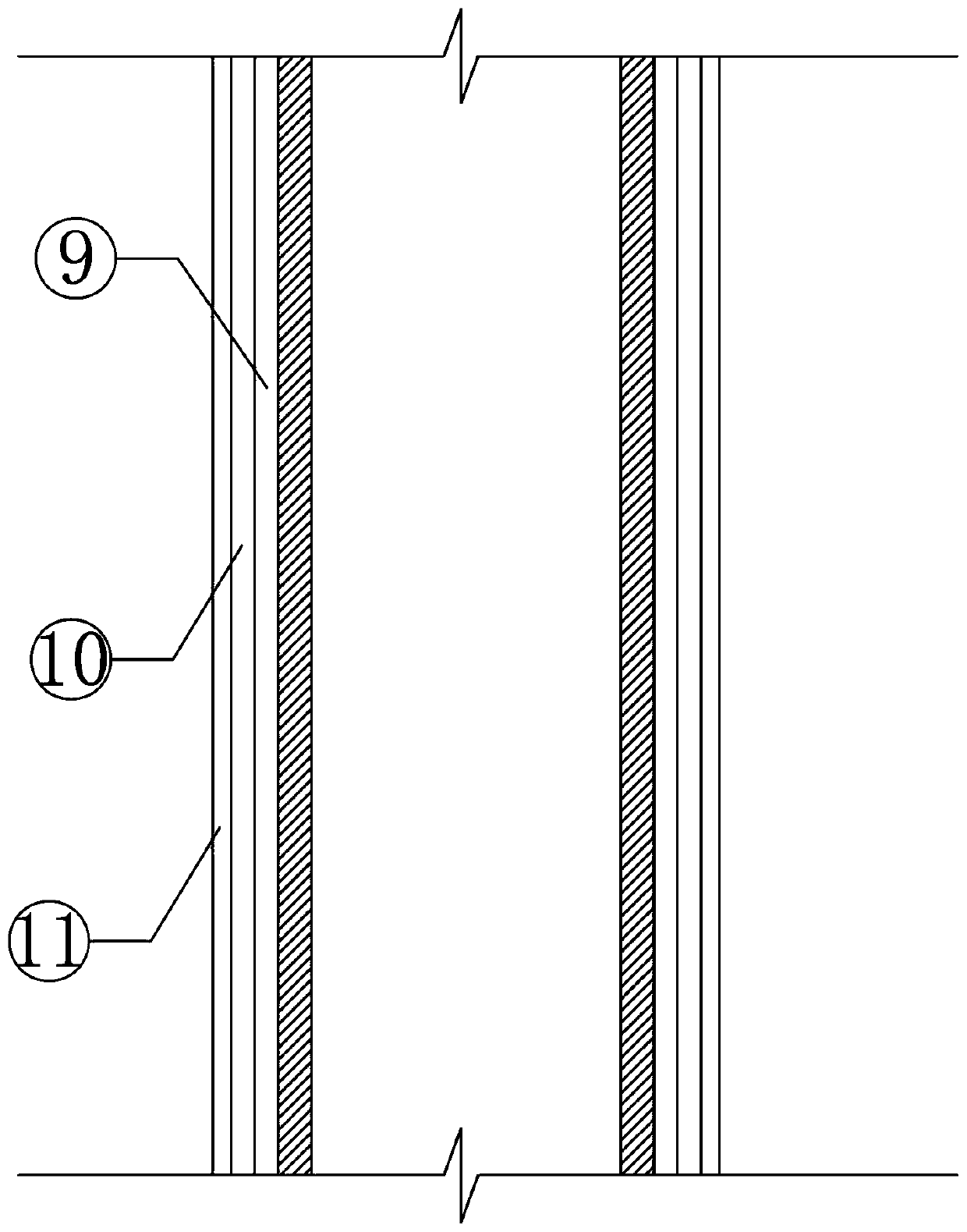
[0018] Embodiments of the present invention will be described in detail below in conjunction with the accompanying drawings. An ice thickness monitoring device based on the principle of water body liquid-solid phase change volume change is fixed by a plexiglass tube 2 and a steel pipe 1 through a waterproof threaded connection 6; A foldable tripod 5 is installed on the tube 2, and a scale 3 is engraved on the plexiglass tube 2; the zero scale of the scale 3 is flush with the outer surface of the steel pipe 1 end; The top cover 4; the end of the steel pipe 1 is fixed with a ball valve 7, the radius of the steel pipe 1 is greater than the radius of the plexiglass pipe 2, and the steel pipe 1 and the plexiglass pipe 2 need to be injected with oil and water at the measurement site. The protective sleeve 8 is composed of a deformable layer 11, an anti-floating layer 10 and an insulating layer 9; the deformable layer 11 does not lose its elasticity in an extremely cold environment, ...


PUM


Abstract

The invention discloses an ice thickness monitoring device and method based on the principle of volume change of liquid-solid phase transition of a water body. The device is composed of an organic glass pipe and a steel pipe fixedly installed together through a waterproof threaded joint. A protective sleeve is fixedly installed outside the organic glass pipe. A scale is engraved on the organic glass pipe, and a foldable tripod is installed on the organic glass pipe. A reversible top cover is installed at the top end of the organic glass pipe. A ball valve is fixedly installed at the end of thesteel pipe. The protective sleeve is composed of a thermal insulation layer, a deformation layer not losing elasticity in an extremely cold environment and an anti-floating layer made of a high-density material. The monitoring method includes the following steps: drilling an ice hole and putting the equipment into the ice hole, injecting a water body, and injecting oil after the liquid level is stabilized; contacting the tail end of the steel pipe with the bottom of the ice layer, and fixing the tripod; and carrying out reading and calculating the ice thickness during monitoring. The ice thickness monitoring device has a simple structure, can run stably and reliably in extremely cold climate and save labor, and facilitates periodic observation at fixed monitoring stations.

Description

technical field [0001] The invention belongs to the technical field of ice layer thickness measurement, and in particular relates to an ice thickness monitoring device and method based on the principle of water body liquid-solid phase change volume change. Background technique [0002] Freezing is a common natural phenomenon in cold regions. Among them, river ice plays an important role in the global climate system, and polar sea ice is an indicator of global climate change. Ice layer thickness is one of the most critical physical indicators in ice science and ice engineering research, a basic parameter to describe the state of river ice, sea ice, and reservoir ice, and one of the key indicators for the force of freezing on hydraulic structures. [0003] For a long time, ice thickness has been generally considered to be the most difficult physical indicator of sea ice or freshwater ice, and manual borehole measurement is the most common detection method to measure ice thickn...

Claims


Application Information

Patent Timeline
Patent Type & Authority Patents(China)
IPC IPC(8): G01B5/06
CPCG01B5/06
Inventor 韩红卫王炳峰陈书超李梦瑶蔡露瑶杨美莹汪恩良
Owner NORTHEAST AGRICULTURAL UNIVERSITY
Why Eureka
Try Eureka