Optical guidance system

A guidance system and optical technology, applied in the field of optical tracking, can solve the problems of poor interface versatility, heavy weight, transportation, deployment, retraction, maintenance inconvenience, etc., and achieve the effect of axis angle conversion.

Active Publication Date: 2019-02-15
BEIJING INST OF RADIO MEASUREMENT
View PDF5 Cites 2 Cited by
  • Summary
  • Abstract
  • Description
  • Claims
  • Application Information

AI Technical Summary

Problems solved by technology

Military binoculars are generally heavy, up to 15kg, plus supporting tripods, counterweight plates and other structural parts, the total weight exceeds 30kg, which is inconvenient in transportation, deployment, withdrawal, maintenance, etc., and poor maintainability
The self-aligning machine used in the mechanical shaft system needs to pass through the SD conversion module before it can communicate with the computer. In addition to using a dedicated SD signal interface between the two, an SD conversion module must be designed on the computer side, using PCI and other buses to communicate with the computer. Communication, poor versatility of interface, high cost

Method used


Image

  • Optical guidance system
  • Optical guidance system
  • Optical guidance system

Examples


Embodiment 1

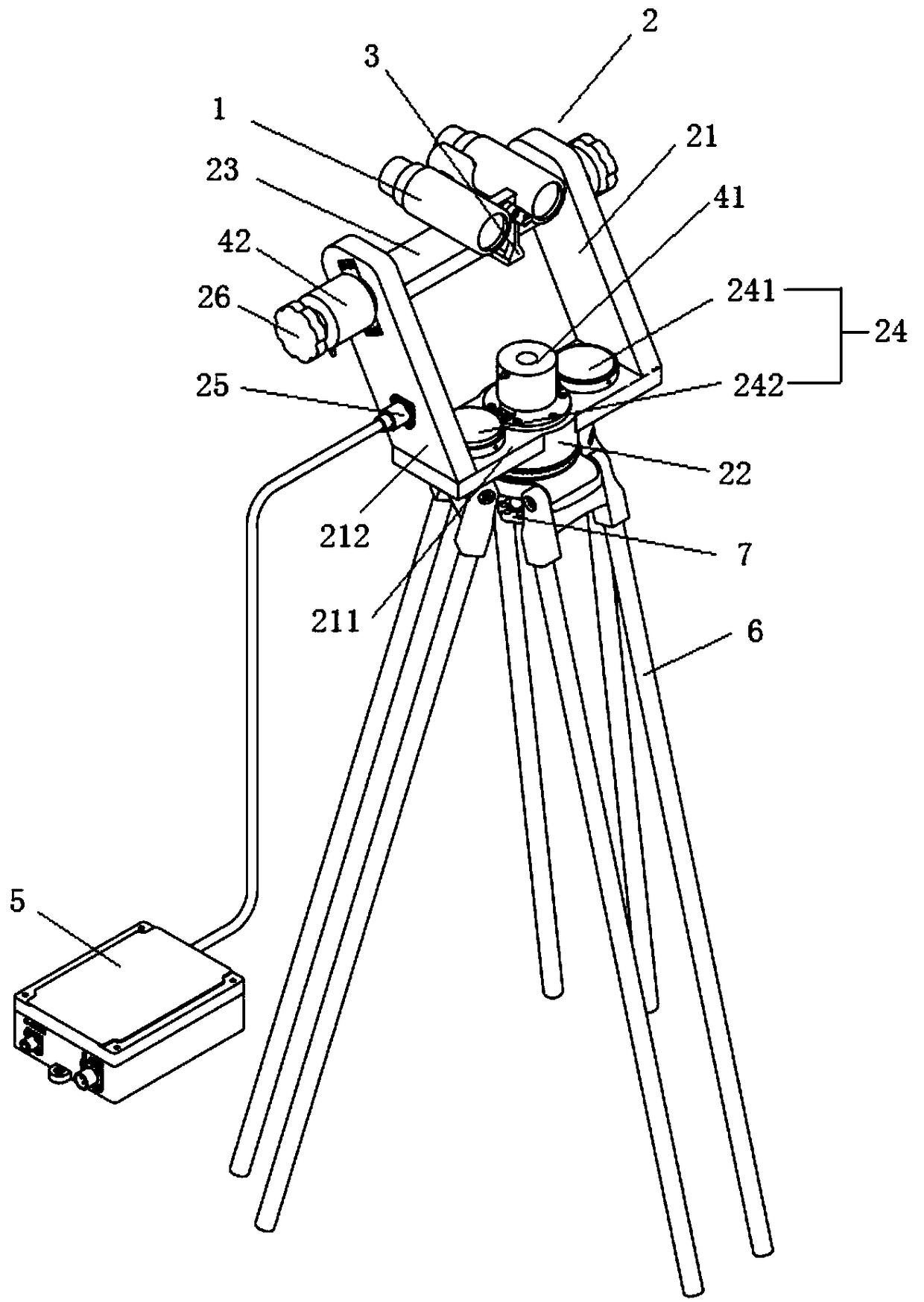
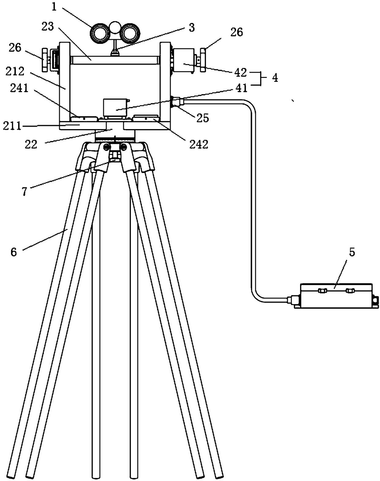
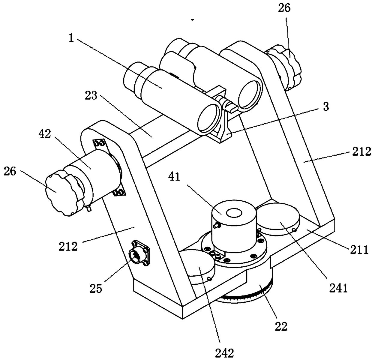
[0037] Such as Figure 1-4 as shown,

[0038] An optical guidance system comprising:

[0039] The turntable 2 is used to adjust the angle of the turntable 2 itself according to the position of the target;

[0040] The benchmark calibration mechanism 24 is used for benchmark calibration of the initial state of the turntable 2 .

[0041] The photoelectric encoder 4 is used to measure the rotation angle of the turntable 2 from the initial state and output the measured value to the terminal.

[0042]The beneficial effects of this embodiment are: the initial state of the turntable 2 itself is calibrated and zeroed by the reference calibration mechanism 24, the angle of the turntable 2 itself is adjusted according to the position of the target to search for the observation target and the tracking target, and the measurement is carried out by the photoelectric encoder 4 The rotation angle of the turntable is obtained and the measured value is output to the terminal. The present in...

Embodiment 2

[0044] Such as Figure 1-4 As shown, an optical guidance system includes:

[0045] The turntable 2 is used to adjust the angle of the turntable 2 itself according to the position of the target;

[0046] The benchmark calibration mechanism 24 is used for benchmark calibration of the initial state of the turntable 2 .

[0047] The photoelectric encoder 4 is used to measure the rotation angle of the turntable 2 from the initial state and output the measured value to the terminal.

[0048] The initial state of the turntable 2 itself is calibrated and zeroed by the reference calibration mechanism 24, the angle of the turntable 2 is adjusted according to the position of the target to search for the observation target and the tracking target, the angle of rotation of the turntable 2 is measured by the photoelectric encoder 4 and The measured value is output to the terminal, and the present invention utilizes the photoelectric encoder 4 to realize shaft-angle conversion.

[0049] S...


PUM


Abstract

The invention relates to an optical guidance system, which includes a turntable used for adjusting the angle thereof according to the position of a target, a reference calibration mechanism used for carrying out reference calibration on the initial state of the turntable, and a photoelectric encoder used for measuring the rotation angle of the turntable relative to the initial state and outputtinga measured value to a terminal. According to the invention, the initial state of the turntable is calibrated and zeroed through the reference calibration mechanism, the target is searched, observed and tracked by adjusting the angle of the turntable according to the position of the target, the rotation angle of the turntable is measured by the photoelectric encoder, and the measured value is output to the terminal. Resolver-to-angle conversion is realized by using the photoelectric encoder.

Description

technical field [0001] The invention relates to the field of optical tracking, in particular to an optical guidance system. Background technique [0002] Optical guidance equipment belongs to the optical telescopic system and is a semi-automatic auxiliary test device commonly used in tracking and measurement radar. When working, use the human eye to find and capture the flying target through the optical imaging of the optical telescopic system, then manually manipulate the optical tracking mechanism to track the target, and send the angle change values ​​of the azimuth and pitch axes to the For the radar system, the servo and antenna are finally controlled in real time, and the target is tracked and measured. [0003] Traditional optical guidance equipment generally includes optical systems, shaft angle conversion systems, mechanical shafting and other parts. The optical part generally uses a military telescope, and the axis-angle conversion is generally realized by a sync...

Claims


Application Information

Patent Timeline
Patent Type & Authority Applications(China)
IPC IPC(8): G01S3/786
CPCG01S3/786Y02A90/10
Inventor 裴万通胡长国
Owner BEIJING INST OF RADIO MEASUREMENT
Why Eureka
Try Eureka