Automatic-pressure-control liquid control container

A container and pressure technology, applied in the field of containers, can solve the problems of insufficient sanitation and environmental protection, and achieve the effect of simple structure

Pending Publication Date: 2019-02-19
陈伟山
View PDF8 Cites 1 Cited by
  • Summary
  • Abstract
  • Description
  • Claims
  • Application Information

AI Technical Summary

Problems solved by technology

[0004] However, since the water-locking structure has been soaked in water for a long time, it is not hygienic and environmentally friendly. Of course, the developers of the above-mentioned mechanical water-locking structure are also aware of this problem and have been working on improvements in this area, but they have not been able to jump out of the partition. Therefore, no matter how it is improved, the fact that its mechanical water-locking structure is soaked in water still exists, and its health problems still exist

Method used


Image

  • Automatic-pressure-control liquid control container
  • Automatic-pressure-control liquid control container
  • Automatic-pressure-control liquid control container

Examples


Embodiment 1

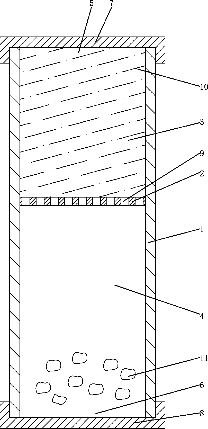
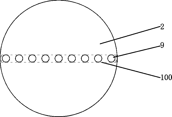
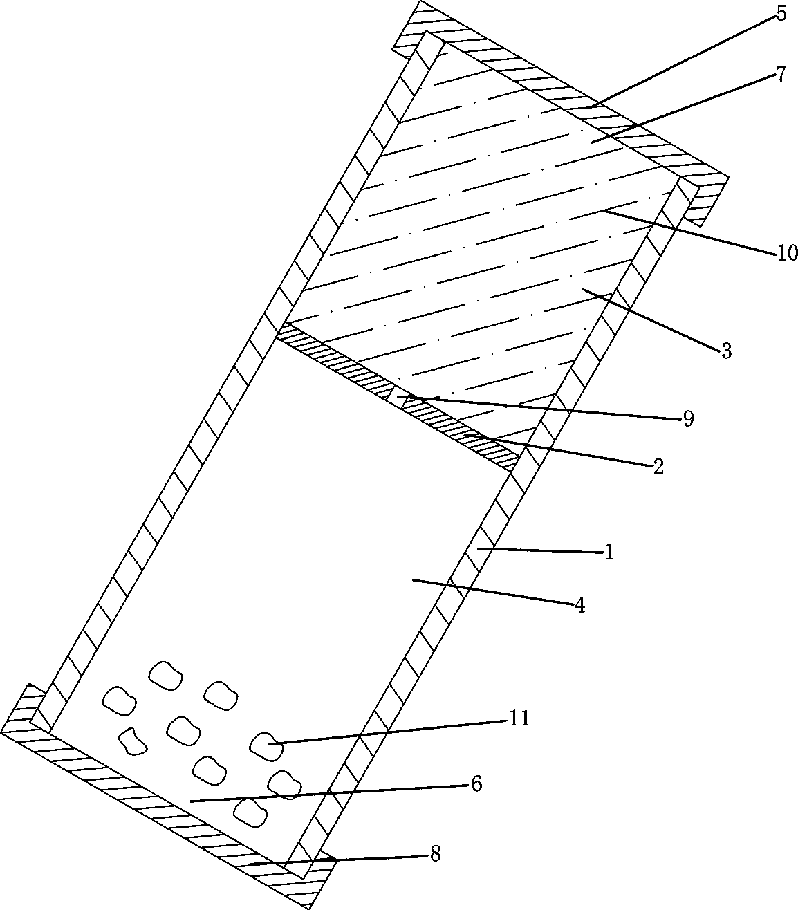
[0030] Such as figure 1 , figure 2 As shown, this pressure self-control liquid control container includes a transparent container 1 and a partition 2, and the partition 2 is arranged in the inner cavity of the transparent container 1 and divides the inner cavity of the transparent container 1 into a first cavity 3 and a second cavity. Two chambers 4, the dividing plate 2 is fixed and sealed connected with the inner wall of the transparent container 1; the transparent container 1 is provided with a first port 5 and a second port 6, the first port 5 communicates with the first cavity 3, and the first port 5 A first sealing end cap 7 is provided on the top, and the second port 6 communicates with the second cavity 4, and a second sealing end cap 8 is provided on the second port 6; a strip-shaped area 100 is provided on the partition 2, and the strip-shaped area 100 is provided with seven water passage holes 9, and each water passage hole 9 is on the same straight line; Inverse...

Embodiment 2

[0043] Such as Figure 5 , Figure 6 As shown, in the case that other parts are the same as the first embodiment, the difference is that: on the strip area 100 on the separator 2, a plurality of water holes 9 are arranged in three rows. The principle of blocking liquid and passing liquid is basically the same as that of Embodiment 1, except that there is a slight difference in blocking liquid: the strip area 100 is in a horizontal state, and the liquid 10 should be completely submerged no matter whether the transparent container 1 is placed vertically, inclined, or horizontally. Only three rows of water holes 9 can block the liquid 10 , and the blocking of the liquid depends more on the surface tension of the liquid 10 .

Embodiment 3

[0045] Such as Figure 7 As shown, in the case that other parts are the same as in the second embodiment, the difference lies in that each water hole 9 is arranged in disorder.


PUM


Abstract

The invention discloses an automatic-pressure-control liquid control container. The container comprises a container body and a partition plate, the partition plate is arranged in an inner cavity of the container body and partitions the inner cavity of the container body into a first cavity and a second cavity, the container is provided with a first port and a first sealing end cover, and a strip-shaped area is arranged on the surface of the partition plate; multiple water-permeating holes are formed in the strip-shaped area, the width of the strip-shaped area is directly proportional to the thickness of the partition plate, and the diameter of each water-permeating hole is inversely proportional to the width of the strip-shaped area. By forming all the water-permeating holes in the partition plate in the container in the strip-shaped area, the strip-shaped area is switched between the horizontal state and the inclined state, and the two functions of stopping liquid and permeating liquid are achieved. The strip-shaped area is in the horizontal state or the inclined state, which is in practice equal to a control switch for controlling switch-on and switch-off, the structure is simple, the limit of traditional mechanical water locking structures is broken through, and the container better accords with the food hygiene and safety standard, and is greener and healthier.

Description

technical field [0001] The invention relates to a container, in particular to a pressure self-control liquid control container. Background technique [0002] The current drinking cup is usually provided with a partition or a filter screen, and the partition is provided with a plurality of through holes, the purpose of which is to block the tea leaves, tea bags, etc. Removed or blocked below the divider, however, the filled water always fills the space under the divider, if the soak is placed under the divider, the soak is always soaked by water, if the soak is placed in Above the partition, people can easily touch the infusion when citing, especially when the infusion is fragmentary tea leaves. [0003] In order to solve the above problems, a mechanical water-locking structure is generally used at present. The mechanical water-locking structure is generally a water hole with a larger aperture on the partition, and then a switch is set on the water hole, such as a cover plat...

Claims


Application Information

Patent Timeline
Patent Type & Authority Applications(China)
IPC IPC(8): A47G19/22
CPCA47G19/2211
Inventor 陈伟山蔡传谋
Owner 陈伟山
Why Eureka
Try Eureka