Hydraulic support pulley

A hydraulic support and pulley technology, applied in the mechanical field, can solve the problems that ordinary oil cylinders cannot meet the requirements of special environments, and achieve the effect of compact structure and improved safety factor

Pending Publication Date: 2019-02-19
上海国一液压气动有限公司
View PDF0 Cites 2 Cited by
  • Summary
  • Abstract
  • Description
  • Claims
  • Application Information

AI Technical Summary

Problems solved by technology

[0002] At present, there is no existing domestic reference technology for comparis

Method used


Image

  • Hydraulic support pulley
  • Hydraulic support pulley
  • Hydraulic support pulley

Examples


Example Embodiment

[0020] In order to make the technical means, creative features, objectives and effects of the present invention easy to understand, the present invention will be further explained below in conjunction with specific embodiments.
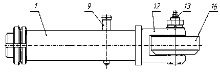
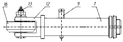
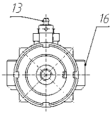
[0021] Reference Figure 1-Figure 8 , This specific embodiment adopts the following technical solutions: hydraulic support pulley, including cylinder barrel 1, parallel cap 2, stop washer 3, piston 4, first seal 5, second seal 6, wear ring 7, return spring 8. Anti-rotation shaft 9, shaft sleeve 10, positioning slider 11, support bracket 12, oil nozzle 13, wheel shaft 14, bearing 15, pulley 16 and oil inlet 17, oil cylinder tube 1 is provided with anti-rotation shaft 9 in the middle of the outer circle, oil cylinder The left end of the barrel 1 is provided with an oil inlet 17, the right end of the cylinder barrel 1 is provided with a support bracket 12, the support bracket 12 is provided with an axle 14, the axle 14 is provided with a pulley 16 through a...


PUM


Abstract

The invention discloses a hydraulic support pulley, which comprises a cylinder barrel, a parallel cap, a locking washer, a piston, a first sealing element, a second sealing element, a wear-resisting ring, a return spring, an anti-rotating shaft, a shaft sleeve, a positioning slide block, a support bracket, an oil nozzle, a pulley shaft, a bearing, a pulley and an oil inlet hole, the middle part ofthe outer circle of the cylinder barrel is provided with the anti-rotating shaft, the left end of the cylinder barrel is provided with the oil inlet hole, the right end of the cylinder barrel is provided with the support bracket, the support bracket is provided with the pulley shaft, the pulley shaft is provided with the pulley through the bearing, and the oil nozzle is arranged above the pulleyshaft. The left end of the cylinder barrel is also provided with the parallel cap through the locking washer, the piston is arranged in the cylinder barrel through the first sealing element and the second sealing element, the piston is internally provided with the return spring, and one end of the return spring is matched with the positioning slide block. The anti-rotating shaft is arranged in thepositioning slide block, the right end of the positioning slide block is fixedly connected with the support bracket. The support bracket is matched with the inner wall of the right end of the cylinder barrel through the shaft sleeve. The pulley has a multi-function effect of anti-rotation and positioning.

Description

technical field [0001] The invention relates to the technical fields of machinery and pneumatic hydraulics, in particular to a hydraulic support pulley. Background technique [0002] At present, there is no existing domestic reference technology for comparison, and ordinary oil cylinders cannot meet the requirements of special environments. Now invent a kind of anti-rotation, positioning, single operation, and form an integrated multifunctional new hydraulic element with the support pulley. The hydraulic support pulley of the present invention is invented by proposing design and using technical parameters in a special environment. Contents of the invention [0003] Aiming at the deficiencies in the prior art, the purpose of the present invention is to provide a hydraulic support pulley, which can solve the problem of anti-rotation, positioning, single operation, and a new hydraulic element integrated with the support pulley. [0004] In order to achieve the above object,...

Claims


Application Information

Patent Timeline
IPC IPC(8): B61C17/00B60L13/04
CPCB61C17/00B60L13/04B60L2200/26
Inventor 施飞
Owner 上海国一液压气动有限公司
Why Eureka
Try Eureka