Foldable sliding driver cab and engineering machine with same

A cab and sliding technology, which is applied in the direction of transportation and packaging, the upper structure of the truck, the upper structure, etc., can solve the problems of restricting the operator's field of vision and large passing height, and improve the convenience of transportation and the comfort of operation , reduce the transport height, and expand the effect of operating vision

Pending Publication Date: 2019-02-19
XCMG CONSTR MACHINERY
View PDF10 Cites 3 Cited by
  • Summary
  • Abstract
  • Description
  • Claims
  • Application Information

AI Technical Summary

Problems solved by technology

The cab of construction machinery is generally fixed as a whole. When transporting the whole machine, a large road passing height is required. At the same time, the existence of the cab limits the operator's field of vision to a certain extent.

Method used


Image

  • Foldable sliding driver cab and engineering machine with same
  • Foldable sliding driver cab and engineering machine with same

Examples


Embodiment Construction

[0020] In order to make the object, technical solution and advantages of the present invention clearer, the present invention will be further described in detail below. However, it should be understood that the specific embodiments described here are only used to explain the present invention, and are not intended to limit the scope of the present invention.

[0021] Unless otherwise defined, all technical terms and scientific terms used herein have the same meaning as commonly understood by those skilled in the technical field of the present invention, and the terms used in the description of the present invention herein are only to describe specific implementations The purpose of the example is not intended to limit the present invention.

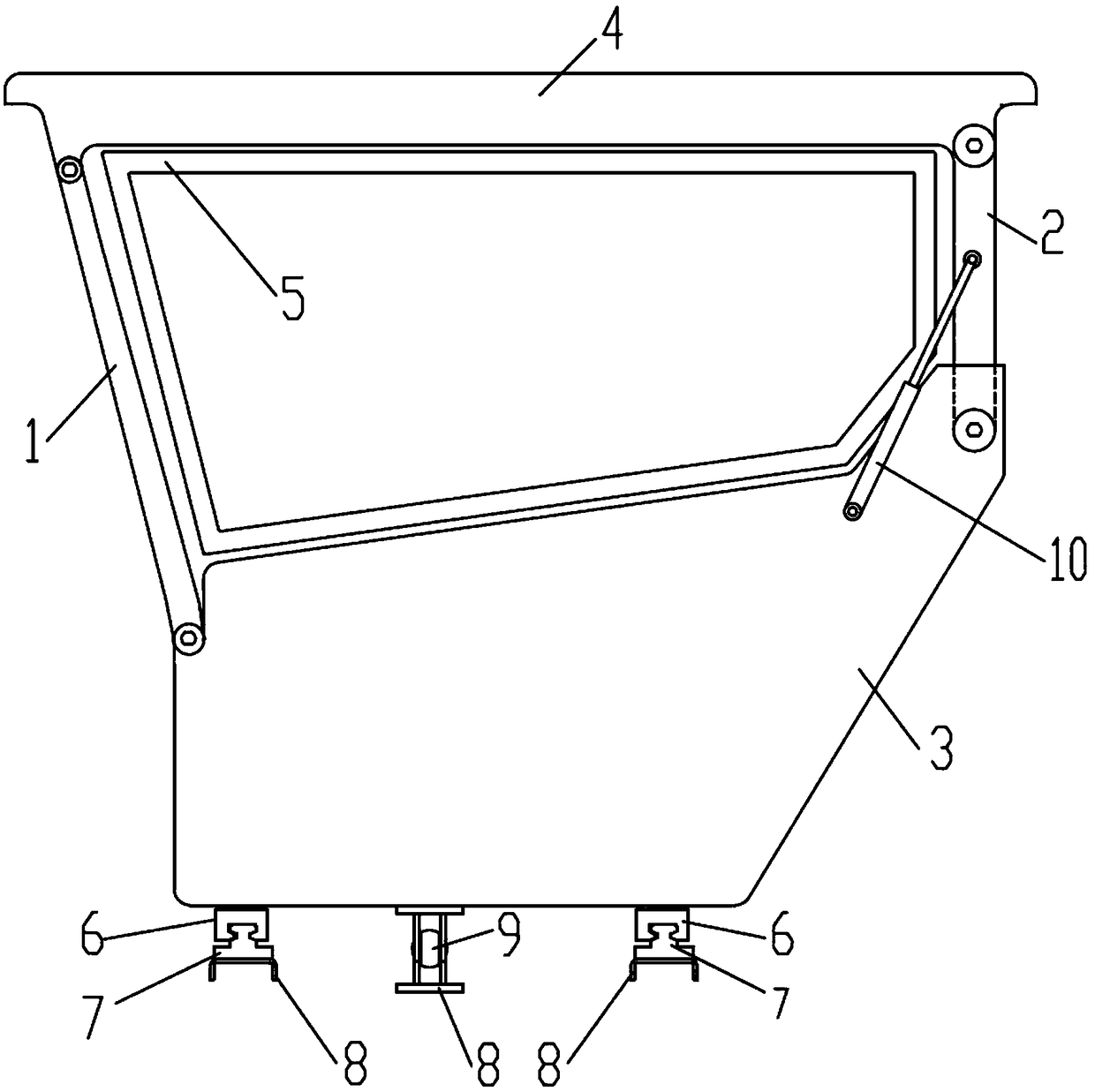
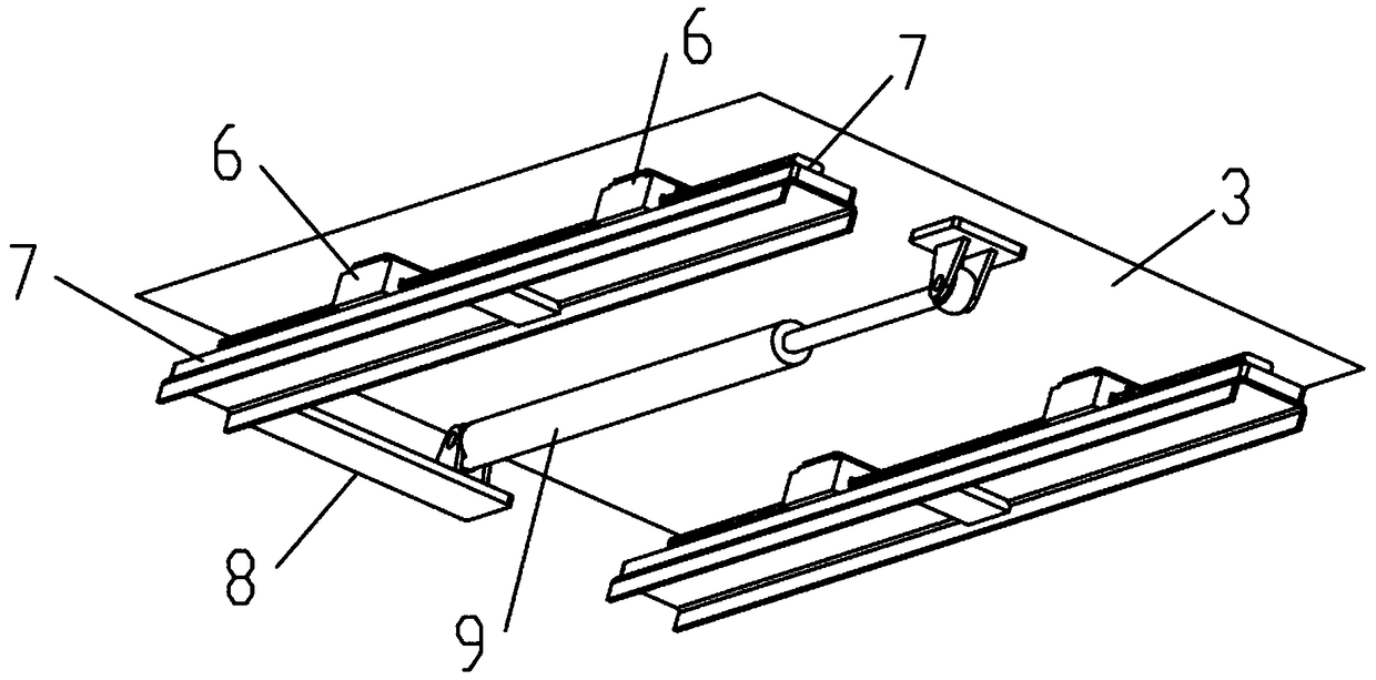
[0022] Such as figure 1 , figure 2 As shown, a foldable sliding cab includes a cab main body, the cab main body is mounted on the vehicle frame 8, and the cab main body is slidingly mounted on the vehicle frame 8;

[0023] The cab mai...


PUM


Abstract

The invention discloses a foldable sliding driver cab. The foldable sliding driver cab comprises a driver cab body mounted on a vehicle frame in a sliding mode; the driver cab body comprises a front frame, a rear frame, a lower frame and a top frame, wherein the top frame is hinged to the upper ends of the front frame and the rear frame, the lower ends of the front frame and the rear frame are hinged to the lower frame, and the front frame, the rear frame, the lower frame and the top frame form a four-bar linkage mechanism; the bottom of the lower frame is provided with a slider, the vehicle frame is provided with a sliding rail matched with the slider, and an oil cylinder I is arranged between the vehicle frame and the lower frame. The four-bar linkage mechanism composed of the front frame, the rear frame, the lower frame and the top frame can achieve folding and adjustment of overall transportation height of the foldable sliding driver cab; the driver cab body is provided with the slider, the vehicle frame is provided with the sliding rail, and sliding of the driver cab can be achieved through movement of the slider on the sliding rail to enlarge the operating view and improve the transportation convenience and operating comfort of an engineering machine.

Description

technical field [0001] The invention relates to a foldable sliding cab and construction machinery installed therein, belonging to the field of construction machinery. Background technique [0002] The cab is an important part of the body, and it is the place where professional drivers work day and night. Its structure is directly related to the driver's safety, work efficiency and health. The cab generally adopts a thin metal shell structure and is flexibly connected to the frame without bearing load, which belongs to the non-load-bearing body. [0003] The cab of construction machinery is used to protect and accommodate operators and improve their working comfort. The cab of construction machinery is generally fixed as a whole. When transporting the whole machine, a large road passing height is required. At the same time, the existence of the cab limits the operator's field of vision to a certain extent. Contents of the invention [0004] In view of the above-mentioned...

Claims


Application Information

Patent Timeline
Patent Type & Authority Applications(China)
IPC IPC(8): B62D33/06B62D33/063
CPCB62D33/0617B62D33/0636
Inventor 刘爱林朱振东宁海莲胡元渊杨波
Owner XCMG CONSTR MACHINERY
Why Eureka
Try Eureka