A kind of UAV multifunctional flap structure

A multi-functional, unmanned aerial vehicle technology, applied in the direction of wing adjustment, etc., can solve the problems of large space, complex slide rail mechanism, difficult to realize, etc., to achieve the effect of improving the effect of increasing lift, improving aerodynamic efficiency, and reducing aerodynamic resistance

Active Publication Date: 2020-08-14
AEROSPACE CH UAV CO LTD
View PDF4 Cites 0 Cited by
  • Summary
  • Abstract
  • Description
  • Claims
  • Application Information

AI Technical Summary

Problems solved by technology

However, the slide rail mechanism is generally more complicated and requires a relatively large space, which is difficult to realize for aircraft with thinner airfoils.

Method used


Image

  • A kind of UAV multifunctional flap structure
  • A kind of UAV multifunctional flap structure
  • A kind of UAV multifunctional flap structure

Examples


Embodiment Construction

[0023] Below in conjunction with accompanying drawing and specific embodiment the present invention is described in further detail:

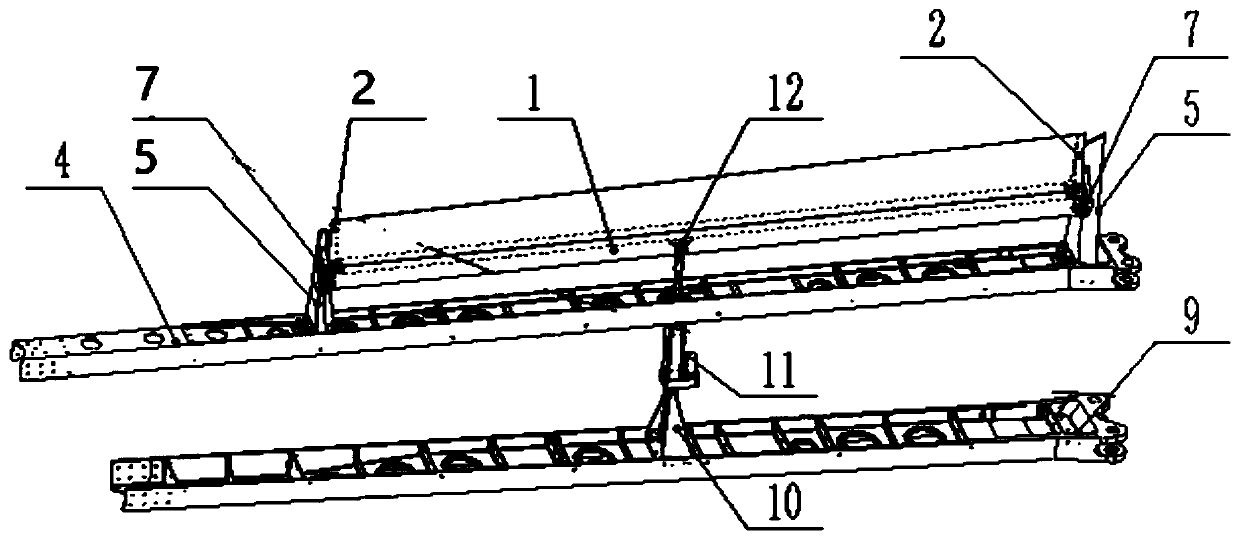
[0024] The invention provides a multifunctional flap structure for an unmanned aerial vehicle, and the rotation axis is below the flap. When the servo drives the flaps to rotate, the flaps will not only rotate at an angle, but also move backwards. With the appropriate airfoil design, the effect of increasing the lift can be improved; when the angle is large, it can also be used as a resistance plate, so as to achieve various Pneumatic function.

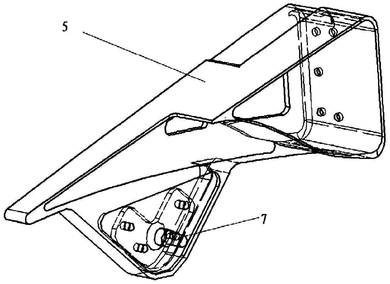
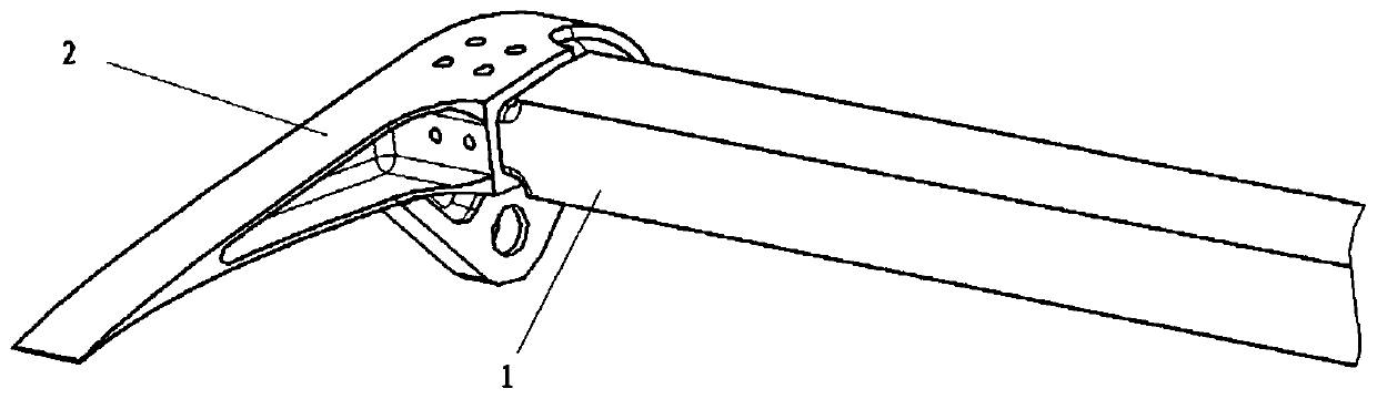
[0025] Such as figure 1 Shown is a schematic diagram of the flap structure. It can be seen from the figure that a multifunctional flap structure for an unmanned aerial vehicle includes a flap bearing beam 1, two end ribs 2, a wing rear beam 4, and two trailing edge ribs 5, 2 A fixed pin shaft 7, wing front beam 9, fixed bearing 10, linear steering gear 11 and tie rod bearing 12; Wherein, wing rear bea...


PUM


Abstract

The invention provides a multifunctional flap structure for an unmanned aerial vehicle, and relates to the field of unmanned aerial vehicle flap design. The multifunctional flap structure for the unmanned aerial vehicle comprises a flap bearing beam, two end ribs, a wing back beam, two trailing edge ribs, two fixed pin shafts, a wing front beam, a fixed support, a linear steering engine and a pullrod support; the wing back beam is placed parallel to the wing front beam; the two trailing edge ribs are fixed on the two axial ends of the wing back beam respectively; the two end ribs are arrangedat the inner side walls of the two trailing edge ribs respectively; each end rib is connected with the corresponding trailing edge rib through the corresponding fixed pin shaft; the flap bearing beamis fixed between the two end ribs in the length direction; the pull rod support is fixed in the middle of the bottom edge of the flap bearing beam; the fixed support is fixed in the middle of the wing front beam; the linear steering engine is fixed at the top end of the fixed support; and the top end of the linear steering engine is hinged to the pull rod support through a joint bearing. The multifunctional flap structure for the unmanned aerial vehicle has the advantages that through driving of the linear steering engine, different aerodynamic functions are achieved, and rotational clampingstagnation of all hinged parts caused by installation error is solved through joint bearings.

Description

technical field [0001] The invention relates to the field of UAV flap design, in particular to a UAV multifunctional flap structure. Background technique [0002] The flaps of the aircraft are generally installed on the leading edge or trailing edge of the wing, and the camber and area of ​​the airfoil are increased by turning or sliding, thereby increasing the lift of the aircraft. When the rotation angle is large, it can also be used as a resistance plate. [0003] In the traditional rotating flap structure, the rotation axis is generally within the section range of the airfoil, and is hinged to the wing box through a pin or hinge. When the flap of this structure is driven, only the angle attitude changes, that is, only the The camber of the airfoil has a limited aerodynamic lift effect. And its transmission mechanism generally protrudes from the outer surface of the airfoil, which increases the aerodynamic resistance. [0004] By designing the slide rail structure, the...

Claims


Application Information

Patent Timeline
Patent Type & Authority Patents(China)
IPC IPC(8): B64C3/50
CPCB64C3/50
Inventor 陈亮李建华李如王若钦刘鑫罗洋
Owner AEROSPACE CH UAV CO LTD
Why Eureka
Try Eureka